


69
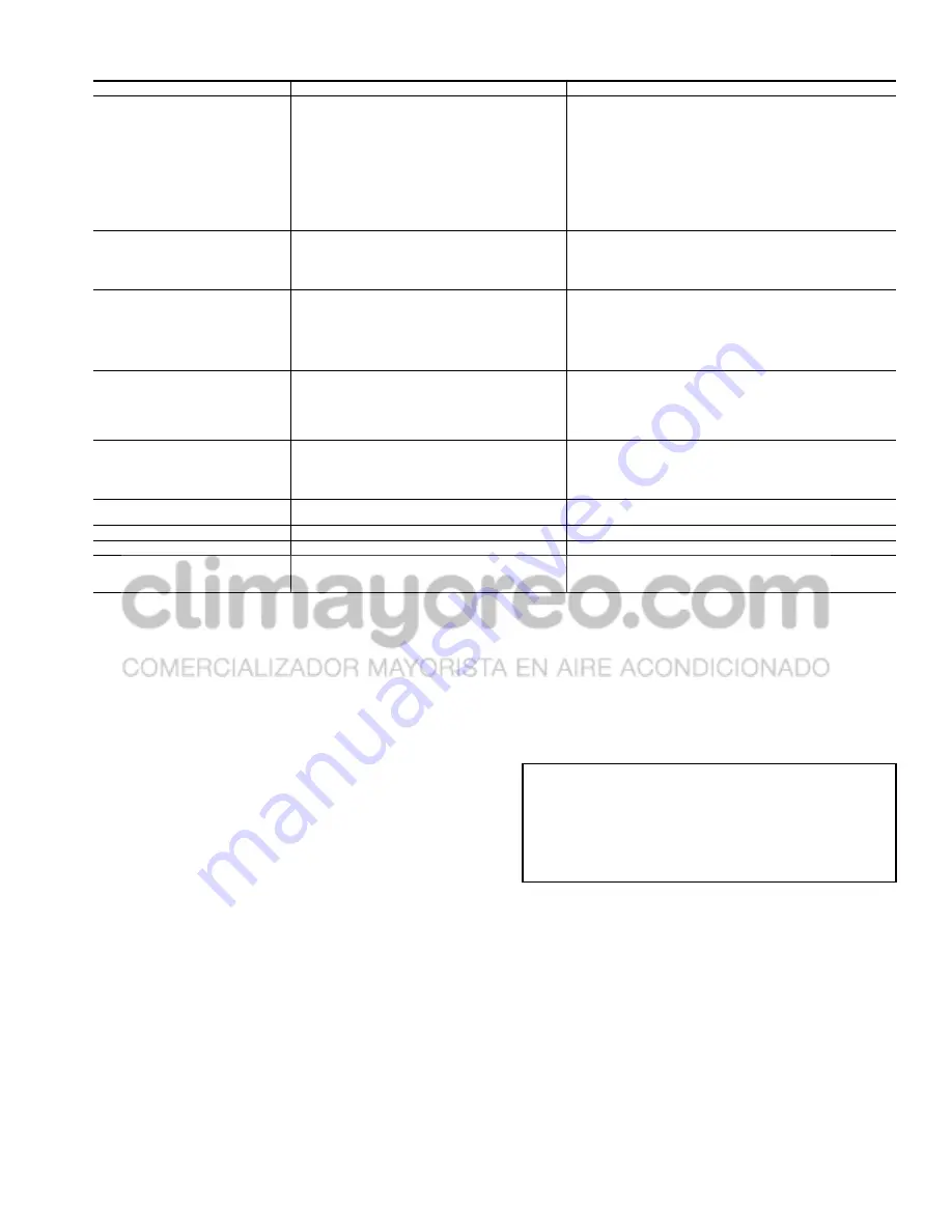
Table 42 — Compressor Control Troubleshooting
Carrier Comfort Network (CCN) Interface —
The 30GX,HX chiller units can be connected to the CCN
if desired. The communication bus wiring is a shielded,
3-conductor cable with drain wire and is supplied and installed
in the field. The system elements are connected to the commu-
nication bus in a daisy chain arrangement. The positive pin of
each system element communication connector must be wired
to the positive pins of each system element. Wiring connec-
tions for CCN can be made at terminal block TB3. There are
four terminals (including shield) located at TB3 for permanent
CCN connection. For temporary CCN connection to the
chiller, there is also an RJ-11 (6 position, 6 conductor) connec-
tor. The connector is for field connection of a laptop computer
running Service Tool or ComfortVIEW™ software programs.
Consult CCN Contractor's Manual for further information.
NOTE: Conductors and drain wire must be 20 AWG (Ameri-
can Wire Gage) minimum stranded, tinned copper. Individual
conductors must be insulated with PVC, PVC/nylon, vinyl,
Teflon, or polyethylene. An aluminum/polyester 100% foil
shield and an outer jacket of PVC, PVC/nylon, chrome vinyl,
or Teflon with a minimum operating temperature range of
–20 C to 60 C is required. Wire manufactured by Alpha (2413
or 5463), American (A22503), Belden (8772), or Columbia
(02525) meets the above mentioned requirements.
It is important when connecting to a CCN communication
bus that a color coding scheme be used for the entire network
to simplify the installation. It is recommended that red be used
for the signal positive, black for the signal negative, and white
for the signal ground. Use a similar scheme for cables contain-
ing different colored wires.
At each system element, the shields of its communication
bus cables must be tied together. If the communication bus is
entirely within one building, the resulting continuous shield
must be connected to a ground at one point only. If the commu-
nication bus cable exits from one building and enters another,
the shields must be connected to grounds at the lightning
suppressor in each building where the cable enters or exits the
building (one point per building only).
Replacing Defective Modules —
The
Comfort
Link™
replacement modules are shown in Table 43. The unit model
and serial numbers are printed on the unit nameplate located on
an exterior corner post (30GX) or the corner of the control box
(30HX). The basic software and unit configuration data is fac-
tory installed by Carrier in the replacement module. Therefore,
when ordering any replacement module, specify the replace-
ment part number (located on each module front or back),
full
unit model number and serial number. The replacement
modules will be downloaded with the basic software. If the
Main Base Board (MBB) has been replaced, verify that all
configuration data is correct. Follow the Configuration mode
table and verify that all items under sub-modes UNIT, OPT1
and OPT2 are correct. Any additional field installed accessories
or options (sub-mode RSET,SLCT) should also be verified.
SYMPTOMS
CAUSE
REMEDY
COMPRESSOR DOES NOT
RUN
Power line open
Control fuse open
High-Pressure Switch (HPS) tripped
Loose terminal connection
Improperly wired controls
Low line voltage
Compressor motor defective
Seized compressor
Pre-lubrication not successful
Check main disconnect.
Check control circuit for ground or short. Replace fuse.
Use Navigator to reset current alarms.
Check connections from CCP to contactor
Check wiring and rewire.
Check line voltage. Determine location of voltage drop
and remedy deficiency.
Check motor winding for open or short. Replace
compressor if necessary.
Replace compressor.
Check oil pump operation, oil pressure transducer, verify oil sole-
noid valve operation.
COMPRESSOR CYCLES
OFF ON LOW SATURATED SUCTION
TEMPERATURE
Loss of charge
Bad transducer
Low refrigerant charge
Failed expansion device
Partially plugged or plugged strainer
Repair leak and recharge.
Replace transducer.
Add refrigerant.
Repair/replace as needed.
Remove and clean strainer.
COMPRESSOR SHUTS
DOWN ON HIGH PRESSURE
CONTROL
High-pressure switch erratic in action
Compressor discharge valve partially closed
Condenser fan(s) not operating (air cooled units)
Condenser coil plugged or dirty (air cooled units)
Condenser water valve not operating (water
cooled units)
Circuit overcharged
Replace switch.
Open valve or replace if defective.
Check wiring. Repair or replace motor(s) if defective.
Clean coil.
Check wiring. Repair or replace valve if defective.
Clean condenser.
UNIT OPERATES LONG OR
CONTINUOUSLY
Low refrigerant charge
Control contacts fused
Partially plugged or plugged strainer
Defective insulation
Service load exceeding design capacity
Inefficient compressor
Add refrigerant.
Replace control.
Clean or replace.
Replace or repair.
Evaluate load requirements.
Check loader solenoid valves. Replace if necessary.
SYSTEM NOISES
Piping vibration
Expansion valve hissing
Compressor noisy
Support piping as required.
Add refrigerant.
Check for plugged liquid line strainer.
Replace compressor (worn bearings).
Check for loose compressor bolts securing compressor to cooler.
COMPRESSOR LOSES OIL
Leak in system
Mechanical damage to rotors
Find and repair leak.
Replace compressor.
HOT LIQUID LINE
Shortage of refrigerant due to leak
Repair leak and recharge.
FROSTED LIQUID LINE
Shutoff valve partially closed or restricted
Open valve or remove restriction.
COMPRESSOR LOADERS
NOT WORKING PROPERLY
Burned out coil
Defective loader solenoid valve
Miswired solenoid
Replace coil.
Replace valve.
Rewire correctly.
IMPORTANT: A shorted CCN bus cable will prevent
some routines from running and may prevent the unit
from starting. If abnormal conditions occur, disconnect
the CCN bus. If conditions return to normal, check the
CCN connections and cable. Run new cable if necessary.
A short in one section of the bus can cause problems
with all system elements on the bus.


