


20
To configure the two chillers for operation, follow the
example shown in Tables 24A and 24B. The master chiller will
be configured with a slave chiller at address 2. Also in this ex-
ample, the master chiller will be configured to use Lead/Lag
Balance to even out the chiller runtimes weekly. The Lag Start
Delay feature will be set to 10 minutes. The chillers will be
configured for parallel fluid flow. The master and slave chillers
cannot have the same CCN address (CCNA, Configuration
mode under OPT2). In addition, the chillers must be connected
together on the same CCN bus. Connections can be made to
the CCN screw terminals on TB3 in both chillers. The master
chiller will determine which chiller will be Lead and which
will be Lag. The master chiller controls the slave chiller by
forcing the slave chiller ON and OFF, and forcing the control
point of the slave chiller. The master chiller will also split
demand limiting function appropriately between the two
chillers, if demand limiting is enabled.
The master chiller is now configured for dual chiller opera-
tion. To configure the slave chiller, only the LLEN, PARA and
MSSL variables need to be set. Enable the Lead/Lag chiller
variable (LLEN) as shown in Tables 24A and 24B. Similarly,
set the Master/Slave Select variable (MSSL) to SLVE. The par-
allel variable (PARA) must be configured the same as the
master chiller. The slave chiller does not use the variables
LLBL, LLBD and LLDY.
It is recommended to set the cooling set points to the same
setting on both Master and Slave chillers for series flow
(Duplex) applications. If outdoor air reset is required the
outdoor air thermistor must be connected to the Slave chiller
(TB5 term. 7 and 8). Outdoor Air Broadcast (BCST, OAT.B)
must be configured “ON”. Remote contacts should be connect-
ed to both Master and Slave to control unit operation. Optional
control inputs and Energy Management Module (EMM)
should be connected to the Master chiller.
Table 11 — Navigator Display Menu Structure
LEGEND
Ckt —
Circuit
RUN
STATUS
SERVICE
TEST
TEMPERATURES
PRESSURES
SET
POINTS
INPUTS
OUTPUTS
CONFIGURATION
TIME
CLOCK
OPERATING
MODES
ALARMS
Auto
Display
(VIEW)
Manual
Mode
On/Off
(TEST)
Unit
Temperatures
(UNIT)
Ckt A
Pressures
(PRC.A)
Cooling
(COOL)
Unit
Discrete
(GEN.I)
Unit
Discrete
(GEN.O)
Display
(DISP)
Unit Time
(TIME)
Modes
(MODE)
Current
(CRNT)
Machine
Hours/Starts
(RUN)
Ckt A/B
Outputs
(OUTS)
Ckt A
Temperatures
(CIR.A)
Ckt B
Pressures
(PRC.B)
Heating
(HEAT)
Ckt A/B
(CRCT)
Ckt A
(CIR.A)
Machine
(UNIT)
Unit Date
(DATE)
Reset
Alarms
(RCRN)
Compressor
Run Hours
(HOUR)
Compressor
Tests
(COMP)
Ckt B
Temperatures
(CIR.B)
Head
Pressure
(HEAD)
Unit
Analog
(4-20)
Ckt B
(CIR.B)
Options 1
(OPT1)
Daylight
Savings
Time
(DST)
Alarm
History
(HIST)
Compressor
Starts
(STRT)
Options 2
(OPT2)
Schedule
(SCHD)
Software
Version
(VERS)
Temperature
Reset
(RSET)
Set Point
Select
(SLCT)
Service
Configuration
(SERV)
Broadcast
Configuration
(BCST)
A
B
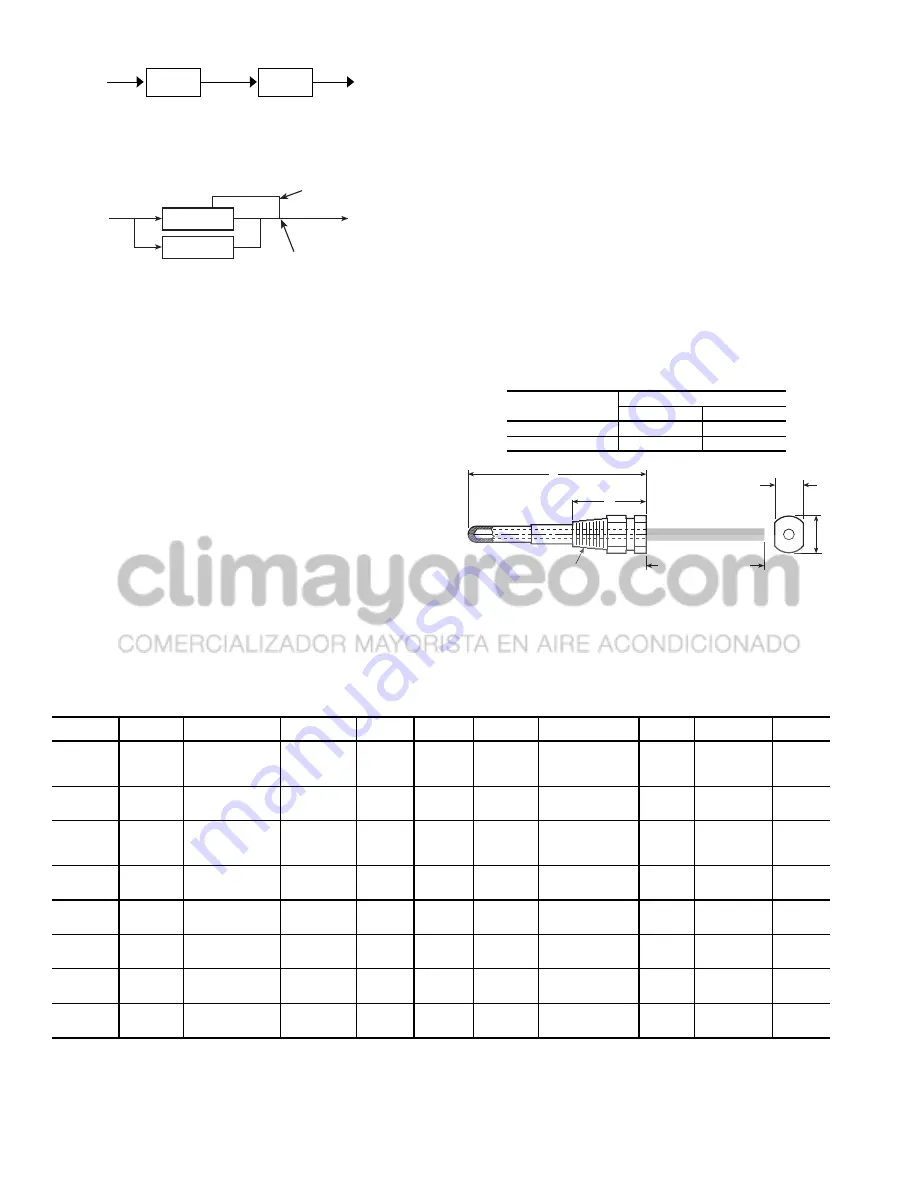
1/4 N.P.T.
0.505/0.495
0.61
DIA
6” MINIMUM
CLEARANCE FOR
THERMISTOR
REMOVAL
Fig. 13 — Dual Leaving Water Thermistor Well
PART
NUMBER
DIMENSIONS in. (mm)
A
B
10HB50106801
3.10 (78.7)
1.55 (39.4)
10HB50106802
4.10 (104.1)
1.28 (32.5)
MASTER
CHILLER
SLAVE
CHILLER
LEAVING
FLUID
RETURN
FLUID
THERMISTOR
WIRING*
INSTALL DUAL CHILLER LWT
LEAVING FLUID TEMPERATURE
THERMISTOR (T9) HERE
Fig. 11 — Dual Chiller Piping Arrangement
(Series Fluid Flow)
* Depending on piping sizes, use either:
• HH79NZ014 sensor/10HB50106801 well (3-in. sensor/well)
• HH79NZ029 sensor/10HB50106802 well (4-in. sensor/well)
Fig. 12 — Dual Chiller Thermistor Location
Parallel Fluid Flow
RETURN
FLUID
SLAVE
CHILLER
MASTER
CHILLER
LEAVING
FLUID


