


4
different colored wires. At each system element, the shields of
its communication bus cables must be tied together. If the com-
munication bus is entirely within one building, the resulting
continuous shield must be connected to a ground at one point
only. If the communication bus cable exits from one building
and enters another, the shields must be connected to grounds at
the lightning suppressor in each building where the cable
enters or exits the building (one point per building only).
To connect the unit to the network:
1. Turn off power to the control box.
2. Cut the CCN wire and strip the ends of the red (+), white
(ground), and black (–) conductors. (Substitute appropri-
ate colors for different colored cables.)
3. Connect the red wire to (+) terminal on TB3, the white
wire to COM terminal, and the black wire to the
(–) terminal.
4. The RJ-14 CCN connector on TB3 can also be used, but
is only intended for temporary connection (for example: a
laptop computer running Service Tool).
Table 1 — Unit Mode from Control/Enable/Off/
Remote Contact and CCN State
LEGEND
NOTE: If the unit is configured for a clock, then the unit is under clock control if
it is in an ON mode.
OPERATION DATA
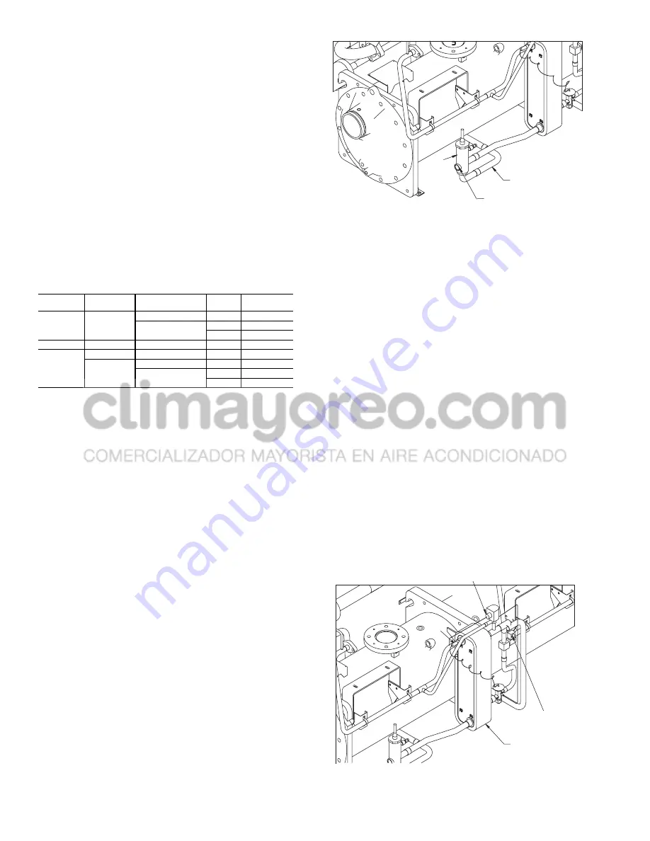
Electronic Expansion Valve (EXV) —
The
MBB
controls the EXV through the EXV board. The EXV (electron-
ic expansion valve) is a device that contains a linear actuator
stepper motor. See Fig. 1.
EXV OPERATION — High-pressure liquid refrigerant enters
the valve through the side. A series of calibrated slots are locat-
ed inside the orifice assembly. As refrigerant passes through
the orifice, the pressure drops and the refrigerant changes to a
2-phase condition (liquid and vapor). To control refrigerant
flow for different operating conditions, the sleeve moves up
and down over the orifice, thereby changing orifice size. The
sleeve is moved by a linear stepper motor. The stepper motor
moves in increments and is controlled directly by the processor
module. As the stepper motor rotates, motion is transferred into
linear movement by the lead screw. Through the stepper motor
and lead screw, 15,000 discrete steps of motion are obtained.
The large number of steps and long stroke result in very accu-
rate control of refrigerant flow.
Each compressor has a discharge gas temperature sensor
mounted vertically in the top of the muffler assembly. The
discharge gas temperature sensor monitors the discharge gas
temperature leaving each compressor and sends this informa-
tion to the MBB through LEN communication with the EXV
board. At initial start-up, the EXV position is at zero. After
that, the microprocessor keeps accurate track of the valve
position in order to use this information as input for the other
control functions. The processor does this by initializing the
EXVs at start-up. The processor sends out enough closing
pulses to the valve to move it from fully open to fully closed,
then resets the position counter to zero. From this point, until
the next initialization, the processor counts the total number of
open and closed steps it has sent to each valve.
ECONOMIZER OPERATION — Economizers are factory
installed on 30GXN,R108,118-350 and associated modular
units and 30HXA,C161-271 units. All other sizes use standard
EXVs. The economizer is a brazed plate heat exchanger
designed to improve chiller capacity and efficiency as well as
providing compressor motor cooling. See Fig. 2. On 30GX
chillers the economizer is active when any compressor is fully
loaded. On 30HXA,C chillers the economizer is active all the
time.
Liquid refrigerant is supplied from the condenser to the
top of the economizer. As the refrigerant passes through the
economizer, its pressure is reduced to an intermediate level.
Next, the refrigerant flows to the EXV which regulates flow to
the cooler to maintain the discharge superheat setpoint.
The increase in performance is achieved by diverting a
small amount of liquid through a thermostatic expansion valve
to a second circuit in the brazed-plate heat exchanger. This will
further subcooling the liquid in the first circuit as the refrigerant
flashes to vapor. This increase in subcooling provides addition-
al capacity. Also, since the additional power required to accom-
plish this is minimal; the efficiency of the machine improves.
The vapor that flashes leaves the top of the economizer where
it passes to the compressor and is used to provide motor cool-
ing. After passing over the motor windings, the refrigerant
reenters the cycle at an intermediate port in the compression
cycle.
SWITCH
POSITION
REMOTE
CONTACTS
CCN
CONFIGURATION
CCN
STATE
UNIT
MODE
ENABLE
NR
DISABLE
NR
LOCAL ON
ENABLE
RUN
CCN ON
STOP
CCN OFF
OFF
NR
NR
NR
LOCAL OFF
REMOTE
CONTACT
OPEN
NR
NR
LOCAL OFF
CLOSED
DISABLE
NR
LOCAL ON
ENABLE
RUN
CCN ON
STOP
CCN OFF
CCN
—
Carrier Comfort Network
NR
—
Input Not Read by Processor
COOLER FEED
SIGHT GLASS
EXV
Fig. 1 — Electronic Expansion Valve (EXV)
TXV
SOLENOID
(30GXN,R ONLY)
BRAZED PLATE
ECONOMIZER
MOTOR COOLING
SOLENOID
TXV
BULB
Fig. 2 — Brazed Plate Economizer


