28
ENG
"humiFog direct" +0300073EN rel. 1.0 - 31.03.2017
8. CONNECTIVITY
8.1 Webserver
The web server is a very interesting function when the user has a local
network available that humiFog Direct can be connected to. The physical
local network connection uses the Ethernet port with RJ45 connector
on the humidifier controller (see Figure 4.G) and a normal Ethernet cable
(category 5).
The integrated web server on the humiFog Direct c.pHC controller is used
to configure and monitor the main unit parameters directly from a PC,
tablet or smartphone.
In fact, using the Ethernet port on the humidifier controller, the humiFog
Direct unit can be accessed via a local network by simply entering its
IP address in the browser (Google Chrome, Internet Explorer, or others).
8.1.1
IP address and network configuration
An IP address is a numerical code that identifies the modem, computer,
smartphone or any other device connected to a network, so as that these
can communicate with one another. Typically the IP address of multiple
devices connected to the same network is identical, except for a few
numbers.
EXAMPLE:
•
192.168.1.1 device #1 connected to the network
•
192.168.1.2 device #2 connected to the same network
•
192.168.2.25 device #3 connected to the same network
Remember that when wanting to connect several devices to the
same network, a switch is required (this can be supplied by Carel, P/N
KITSE08000).
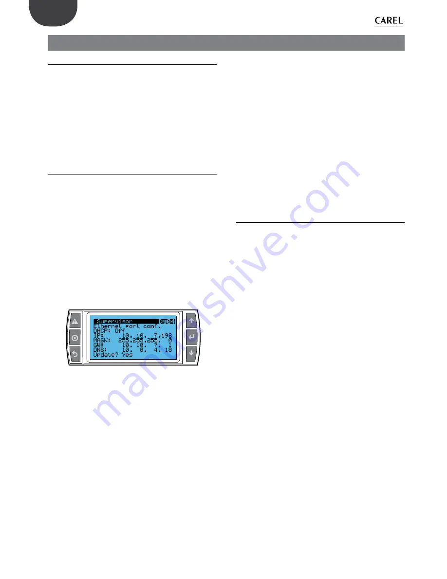
The IP address of the humiFog Direct unit is shown on the display, under:
•
D. Settings
•
d. Unit networks
•
g. Supervisor
Dg04. Ethernet supervision port configuration: DHCP and IP address
Fig. 8.a
Simply copy the numerical code (10.10.7.198 in the example in Figure 8.a)
into internet address bar to access the humidifier’s web server.
IP addresses may be :
•
dynamic (if using the DHCP function that automatically assigns an IP
address when a device is connected)
•
static (if there is no DHCP function or it cannot be used, with manual
assignment of the IP address directly by the user).
If using a dynamic IP address via the DHCP function on the server,
DHCP needs to be enabled on screen Dg04 on the humiFog Direct
unit. The IP address shown on the screen will be assigned automatically.
The advantage of this feature is that the server and humiFog Direct
communicate directly, and there is no need to configure the network
parameters (subnet mask and gateway). The disadvantage is that if
adding other devices to the same network with humiFog Direct off and
not connected, the IP address originally assigned to the unit may change,
and therefore the new address needs to be set on screen Dg04 and
copied into the browser’s address bar.
With a static IP address (with DHCP OFF as by default), on screen Dg04
enter the network parameters manually, as provided by the local network
installer. Usually subnet mask and gateway have predefined values (which
must be known), while the IP address can be assigned sequentially in
relation to another device connected to the same network.
The default network configurations for the c.pHC are:
•
unit IP address: 192.168.0.1
•
subnet mask: 255.255.255.0
•
gateway: 192.168.0.1
Important:
in the “capacity extension” function (described in paragraph
6.4), DHCP cannot be activated, otherwise the units would not be able
to communicate together. DHCP must be disabled on screen Dg04 (as
by default).
Important:
the controller is not accessible directly via the internet as a
firewall guarantees remote access only over a secure connection (Carel
tERA cloud connection). Consequently, outside of the local network the
controller cannot be accessed, even if the network administrator assigns
a public address.
8.1.2
Web server functions
Once having entered the web server, the login to access the various
menu items requires the installer or service password (default 0077). The
web server “home” provides direct access to a virtual display, allowing all
the settings to be made in the same way as directly on the unit’s actual
display. In addition, an immediate response in terms of unit operation will
be available on the interface overview. The following menus are available
on the interface:
UNIT:
•
Probes: information on the probe readings and the main and limit
probe configuration. Select the type of signal and define the minimum
and maximum values.
•
Wireless: enable and associate each wireless probe to the group of
main probes or limit probes. Read humidity and/or temperature,
wireless probe signal level and battery charge.
•
Control: select the type of control. Set the set point, differential and
minimum / maximum.
•
Scheduler: enable and set the daily and weekly time bands
NETWORK:
•
Display a summary of the status of the units in the Master/Slave system.
MAINTENANCE
•
Timers: display unit operating hours. Display time remaining until
maintenance and set maintenance pre-alert.
•
Logs: display the log of main variables (production, set point, pump
status, request, unit status).
•
Live: display the main variables in real time (production, set point,
pump status, request, unit status).
INFO
•
Unit info: information on the unit model and software version. Select
language and unit of measure.
•
Resources: useful links (Carel website, manuals and humiFog Direct
page on the Carel website).
•
Guide & FAQ: general information on using the web server.
Important:
to avoid unwanted modifications, some of the main operating
and unit parameters can only be set on the web server when the unit is
off (off from keypad, settable on the web server).
Summary of Contents for humiFog direct
Page 2: ......
Page 4: ...4 ENG humiFog direct 0300073EN rel 1 0 31 03 2017...
Page 6: ...6 ENG humiFog direct 0300073EN rel 1 0 31 03 2017...
Page 43: ......


