14
ENG
"humiFog direct" +0300073EN rel. 1.0 - 31.03.2017
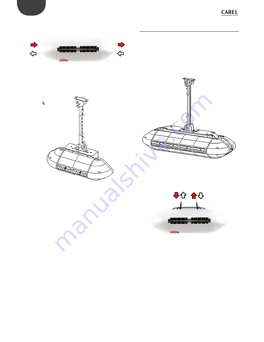
Then make the water connections, connecting the feedwater line
either on the right or left of the blower, and the water return line on the
opposite side.
Fig. 3.e
Finally, fit the two cable glands and complete the electrical wiring, as
described in paragraph 3.4.
Carel also provides an additional kit (including a special plate bent at 90°)
for mounting single blower units on the ceiling.
Fig. 3.f
3.3 Mounting double blower units on the
ceiling
The double blower units (P/N DLA%B) are designed to be installed on
the ceiling by anchoring them to a metal support that can support their
weight and the vibrations due to the pressurised water. To mount the
blower unit, use the special attachments provided on the unit’s metal
structure.
Carel provides additional kits with everything needed to complete
installation easily. Make sure to carefully choose the point where the
vertical support bar will be anchored. The support bar must not be longer
than 1 metre, so as to avoid excessive bending and vibrations.
Fig. 3.g
After installing the blower, make the water connections by connecting
the feedwater and return lines to the two pipes provided on the top of
the blower. The feedwater/return lines can be connected either to the
right or left.
Fig. 3.h
Finally, fit the two cable glands and complete the electrical wiring, as
described in paragraph 3.4.
Summary of Contents for humiFog direct
Page 2: ......
Page 4: ...4 ENG humiFog direct 0300073EN rel 1 0 31 03 2017...
Page 6: ...6 ENG humiFog direct 0300073EN rel 1 0 31 03 2017...
Page 43: ......


