Carel EVD4 User Manual Download Page 36

36

ENGL

ISH

EVD

4

 +030220227 - rel. 2.1 - 12.06.2008 
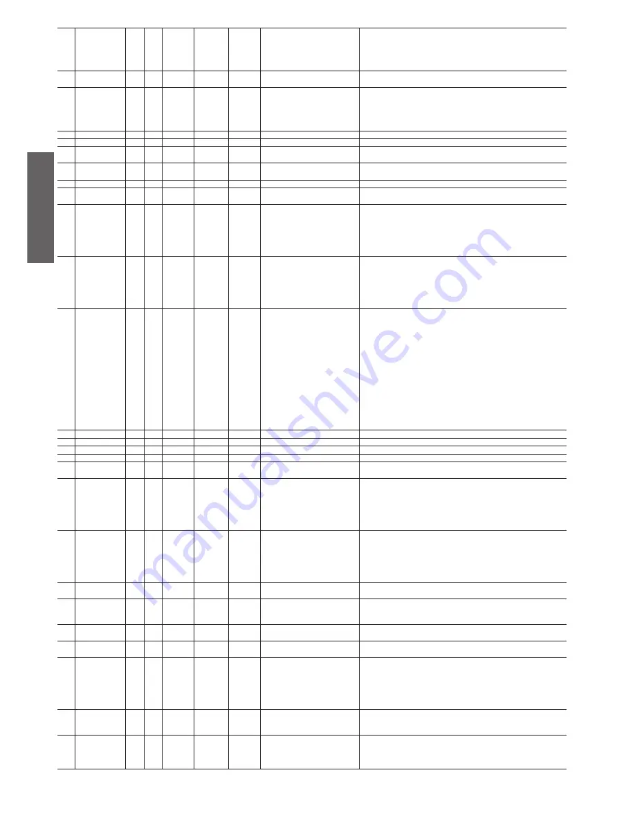
Dynamic proportio-
nal gain

I

71

0,6

0,6

0,6

attenuation coeffi cient with change in 
capacity

Parameter active for each change in capacity of the circuit: when the driver pre-posi-
tions the valve (see CH-Circuit/EEV Ratio, HP-Circuit/EEV Ratio, and DF-Circuit/EEV 
Ratio); the difference between the initial and the fi nal position is multiplied by value 
of this parameter, between 0 and 1, and the effect of the change in capacity on the 
SH is attenuated.

EEV mode man.

D

68

0

0

0

enable/disable manual valve positioning Enables/disables manual valve positioning, eliminating the activation of any control 

or alarm

EEV not closed

D

47

0

0

0

active due to failed valve closing

If the EVD400 is installed with a backup battery, in the event of mains power failures 
or no communication with the controller for more than 30 sec, the valve is closed. 
If during this procedure EVD400 cannot control all the steps to close the valve due 
to lack of backup power (fl at battery), when restarting the EEV not closed error is 
displayed, with the consequent Go ahead request

EEV opening

A

17

0

0

0

valve opening as a %

Controlled opening of the valve as a %

EEV position

I

15

0

0

0

calculated valve opening position

Calculated opening of the valve, in steps

En. positioner

I

63

enable/disable manual positioner 
function

Enables/disables the manual positioner function, from pCO

Enable reset to 
default

I

1

0

0

0

enable restore default parameters

If set to 14797, allows the user to reset all the parameters to the default values by 
enabling the Reset to default variable

Ev. probe press.

A

14

0

0

0

evaporation pressure value measured

Value measured by the evaporation pressure probe

Ev. probe sat. temp. A

16

0

0

0

saturated gas temperature value calcula-
ted in the evaporator

Saturated gas temperature value calculated in the evaporator, taken from the evapora-
tion pressure on the Mollier chart

Evaporator type 
cool

type of evaporator in CH mode

“Identifi es the type of exchanger used as the evaporator in cooling mode:
1 • Plates
2 • Shell&tube
3 • Fast fi nned
4 • Slow fi nned
This section confi gures the integral time in the PID control parameters.”

Evaporator type 
heat

type of evaporator in HP mode

“Identifi es the type of exchanger used as the evaporator in heating mode:
1 • Plates
2 • Shell&tube
3 • Fast fi nned
4 • Slow fi nned
This section confi gures the integral time in the PID control parameters.”

EVD probes type

I

69

0

0

0

type of sensors used

“Number that indicates the combination of sensors used to calculate the superheat 
value; the default value 51 corresponds to a ratiometric probe connected to S1 and 
a 103 AT NTC sensor temperature to S3. For other connections, set the value of the 
parameter according to the following formula:
EVD probes type = CFGS1 + 5 * CFGS2 + 25 * CFGS3where:
CFGS1 (probe on channel S1) = 0, 1 or 2
CFGS2 (probe on channel S2) = 0, 1, 3 or 4
CFGS3 (probe on channel S3) = 0, 1 or 2
and:
0 = no measurement
1 = ratiometric pressure
2 = NTC 103AT (10000 ohm at 25 °C)
3 = NTC IHS (50000 ohm at 25 °C)
4 = Pt1000”

EVD type

model of EVD used

Model of EVD used, from pCO

EVD version H.W

I

100

0

0

0

driver hardware version

Driver hardware version

EVD version S.W

I

100

0

0

0

software version installed on the driver

Software version installed on the driver

Force         

D

8

0

0

0

send a FORCE command to the EVD

Transmission of all the parameters or variables

Functional test

D

2

0

0

0

functional test

The functional test is a status of the driver that is used to check the operation of the 
device, and in particular to calibrate a number of variables

Go ahead

D

35

0

0

0

enable restart following error

“When the driver signals one of the following errors:
- Probe error alarm
- EEPROM error alarm
- EEV not closed
authorisation is requested continue after the user has checked the existence and the 
seriousness of the problem.”

Heat

type of evaporator in HP mode

“Identifi es the type of exchanger used as the evaporator in heating mode:
1 • Plates
2 • Shell&tube
3 • Fast fi nned
4 • Slow fi nned
This section confi gures the integral time in the PID control parameters.“

Hi TCond. int. time A

36

0

0

0

integral time for high condensing 
temperature control (HiTcond)

Integral time for high condensing temperature control, see Hi TCond. protection

Hi TCond. 
protection

A

40

80

80

80

maximum condensing temperature

Maximum condensing temperature; once exceeded, the driver starts controlling 
the valve position based on this set point and considering the Hi TCond. int. Time 
parameter

High superheat 
alarm threshold

A

37

200

200

200

maximum superheat temperature

Maximum superheat temperature. If HP and DF modes are also available, this refers 
to control in CH mode

High Tc status

D

53

0

0

0

active when in high condensing tempe-
rature control status

Active when in high condensing temperature control mode, see Hi TCond. protection

HP-Circuit/EEV 
Ratio

I

20

percentage of the maximum capacity 
managed by the valve in HP mode, 
from pCO

This is the ratio between the maximum cooling capacity delivered by the valve and 
the maximum in the circuit, in HP mode. Used to pre-position the valve when starting 
and changing capacity, sent by the pCO or µC

2

 controller (e.g. if the capacity of the 

system changes to 50%, the pCO or µC

2

 tells the driver to preposition the valve at 

50% of its total travel, minus the Dynamic proportional gain factor, then the driver will 
commence independent SH control), from pCO or µC

2

.

HP-Integral time

A

29

35

35

200

integral time for superheat control in 
HP mode

This is the time of the PID integration action for operation in HP mode, increasing 
the value the SH reaches the set point more slowly but avoids excessive swings. This 
depends on the type of evaporator and the inertia of the circuit.

HP-Low Superheat

A

44

3

3

6

low superheat value in HP mode

This is the minimum SH value below which the system activates the Alarm Low 
Superheat after the Alarms delay Low SH in the operation in HP mode. This is used to 
avoid an excessively low pressure difference between the condenser and evaporator 
circuits, which may cause liquid at the compressor intake.

Summary of Contents for EVD4

Page 1: ...EVD4 Driver for electronic expansion valve User manual...

Page 2: ......

Page 3: ...User manual...

Page 4: ...n at its best for the specific application The lack of such phase of study as indicated in the manual can cause the final product to malfunction of which CAREL can not be held responsible Only qualifi...

Page 5: ...er EVD000 40 and EVD000 43 17 3 4 Application with pCO EVD000041 and EVD000044 via pLAN 19 3 5 Application with supervisor EVD000 42 and EVD000 45 via RS485 22 3 6 Application with Modbus protocoll EV...

Page 6: ...6...

Page 7: ...d step up transformer for backup power supply EVBAT00300 System made up of EVBAT00200 12 V 1 2 Ah battery cable and connectors EVBATBOX10 Metal battery case CVSTDUTTL0 USB converter to connect a PC to...

Page 8: ...troller The converter can power the logical section of the EVD4 but not the expansion valve and therefore this can be configured from the PC without having to connect the instrument to the 24 Vac powe...

Page 9: ...sed as power supply to the ratiometric probes S1 Analogue input for ratiometric probe or NTC low temperature probe S2 Analogue input for ratiometric probe NTC high temperature probe or Pt1000 S3 Analo...

Page 10: ...r cable Fig 2 8 Connect the USB cable to the PC if the EVD4 is not powered by the 24 Vac line it will take its power supply from the serial converter Once the supervisor has been connected start an ap...

Page 11: ...roller with a different communication protocol e g EVD000 40 with pCO via pLAN and is then connected to a unit with the same protocol e g EVD000 40 with pCO or C2 via tLAN the first time that the EVD4...

Page 12: ...ttenuation coefficient with change in capacity SHeat dead zone dead zone for PID control Derivative time PID derivative time Low SHeat int time integral time for low superheat control LOP integral tim...

Page 13: ...tatus LOP status active when in minimum evaporation pressure control status High Tc status active when in high condensing temperature control status alarm Eeprom error active following an EEPROM memor...

Page 14: ...applications In the standard application the EVD4 read and write parameters are organised into three groups accessible from a pCO terminal input output maintenance and manufacturer The SYSTEM SET leve...

Page 15: ...de temperature at minimum operating pressure MOP in CH mode Heat Mode temperature at minimum operating pressure LOP in HP mode Defr Mode temperature at minimum operating pressure LOP in DF mode MOP Co...

Page 16: ...offset S2 correction of the lower limit of S2 Probes offset S3 correction of the lower limit of S3 ADVANCED SETTINGS SPECIAL TOOLS Not available ALARMS for driver X Parameter name Description alarm pr...

Page 17: ...ed to start operation Secondary parameters required for optimum operation Advanced parameters WRITE Parameter name Description Mode dependent parameters Fig 9 Calibr S4 gain mA current gain on channel...

Page 18: ...re described in 3 3 3 as follows Power up the EVD4 from the mains or via converter Connect EVD4 to the PC via the converter Set S4 probe type 5 configuration of input S4 as 4 to 20 mA or 6 0 to 10 V C...

Page 19: ...led in the system Selecting the type of driver and enabling any advanced functions will allow access to specific fields masks in this or other menus The AUTO SETUP level of parameters must also be com...

Page 20: ...tegral time integral time for superheat control in CH mode CH Low Superheat low superheat value in CH mode heat mode adjust HP Circuit EEV Ratio percentage of the maximum capacity managed by the valve...

Page 21: ...om the probe alarm Eeprom error active following an EEPROM memory error alarm MOP timeout active in conditions with excessive evaporation pressure alarm LOP timeout active in conditions with insuffici...

Page 22: ...Prop gain PID proportional factor CH Integral time integral time for superheat control Advanced I SH dead zone dead zone for PID control Derivative time PID derivative time CH Low Superheat low superh...

Page 23: ...cient evaporation pressure EEV not closed active due to failed valve closing Low SH status active when in low superheat control status MOP status active when in maximum evaporation pressure control st...

Page 24: ...erheat control LOP integral time integral time for low evaporation pressure LOP control MOP integral time integral time for high evaporation pressure MOP control Alarms del Low SH low superheat alarm...

Page 25: ...p pendix I Installing and using the EVD4 UI program within the envisaged range Values from 248 to 255 are reserved If set to one of these values or 0 the FW sets the default value without modifying th...

Page 26: ...OGUE R ONLY REGISTER 50 to 86 ANALOGUE R W REGISTER 128 to 150 INTEGER R ONLY REGISTER 163 to 231 INTEGER R W COIL 1 to 20 DIGITAL R ONLY COIL 51 to 84 DIGITAL R W The correspondence between the Carel...

Page 27: ...I R W 8 REGISTER R W 170 I R W 9 REGISTER R W 171 I R W 10 REGISTER R W 172 I R W 11 REGISTER R W 173 I R W 13 REGISTER R W 174 I R W 14 REGISTER R W 175 I R W 16 REGISTER R W 176 I R W 17 REGISTER R...

Page 28: ...OIL R 12 D R 46 COIL R 13 D R 47 COIL R 14 D R 49 COIL R 15 D R 50 COIL R 16 D R 51 COIL R 17 D R 52 COIL R 18 D R 53 COIL R 19 D R 64 COIL R 20 D R W 1 COIL R W 51 D R W 2 COIL R W 52 D R W 3 COIL R...

Page 29: ...uired configuration The interface configuration for the positioner function is shown in Fig 3 21 and is activated by making the EVD4_UI stand alone connection as described in APPENDIX I INSTALLING AND...

Page 30: ...y if the optional EVBAT00200 300 module is installed power supply is guaranteed to the controller for the time required to close the valve Inputs and outputs Analogue inputs input type CAREL code S1 S...

Page 31: ...verage value observed if the swing stops re enable automatic operation and set less reactive parameters decrease the proportional factor increase the integral time Bubbles of air can be seen in the li...

Page 32: ...requires write access to the configuration files Open the IN EVD400UI INI file from the path where EVD4_UI exe is located and make sure that the Paddr parameter is set to 1 Start the EVD4_UI program...

Page 33: ...n Meaningoftheredorgreenrectangle GREEN FALSEorOFFor0orDISABLED inrelationtothemeaningofthereferenceparameter RED TRUEorONor1orENABLED inrelationtothemeaningofthereferenceparameter if the checkbox is...

Page 34: ...essure LOP alarm delay This is the time that passes from when the superheat temperature is continuously less than the value set for LOP cool mode or LOP Defr Mode or LOP Heat Mode to when the user wan...

Page 35: ...arameters and the auxiliary Driver protectors considering the control characteristics of the various types of system 1 Reciprocating 2 Screw 3 Scroll 4 Flooded cabinet 5 Cabinet Cond probe press A 12...

Page 36: ...ment 1 ratiometric pressure 2 NTC 103AT 10000 ohm at 25 C 3 NTC IHS 50000 ohm at 25 C 4 Pt1000 EVD type model of EVD used Model of EVD used from pCO EVD version H W I 100 0 0 0 driver hardware version...

Page 37: ...22 30 30 30 minimum control steps Position below which the valve is considered closed This parameter is only used during repositioning see CH Circuit EEV Ratio MODE I 16 0 0 0 READ ONLY received from...

Page 38: ...ut S1 4 5 V S1 probe limits Min I 41 1 1 1 zero scale for pressure sensor on input S1 Pressure value corresponding to the minimum of ratiometric output S1 0 5 V S2 Pt1000 calib I 68 0 0 0 calibration...

Page 39: ...s not completely closed and attempts to close it by performing Maximum steps 128 steps every second until the SH reaches coherent values The procedure is stopped if the condition persists for Maximum...

Page 40: ...patibility with the chosen refrigerant The following values are recommended as a reference and starting point for the configuration of the EVD400 and the PID control The users can then check whether o...

Page 41: ...dt Ti oppure u t K e t 1 e t dt Td de t dt This means that the control is calculated as the sum of three contributions P or proportional action Ke t k proportional gain I or integral action Ti K e t d...

Page 42: ...is Kp 100 BP In the first diagram in Fig 3 Bp 50 hence Kp 2 while in the second BP 10 and thus Kp 10 The proportional action of the PID controllers is set by the operator as the proportional band cha...

Page 43: ...alue of the derivative time Tp decreases swings however there may be fluctuations around the set point The derivative action makes the control depend on the future of the error that is on the directio...

Page 44: ...44...

Page 45: ..._________________________________________________________ _______________________________________________________________________________________ ______________________________________________________...

Page 46: ..._________________________________________________________ _______________________________________________________________________________________ ______________________________________________________...

Page 47: ......

Page 48: ...CAREL S p A Via dell Industria 11 35020 Brugine Padova Italy Tel 39 049 9716611 Fax 39 049 9716600 e mail carel carel com www carel com Agenzia Agency 030220227 rel 2 1 12 06 2008...

Reviews: