docs.carbide3d.com
60
3.
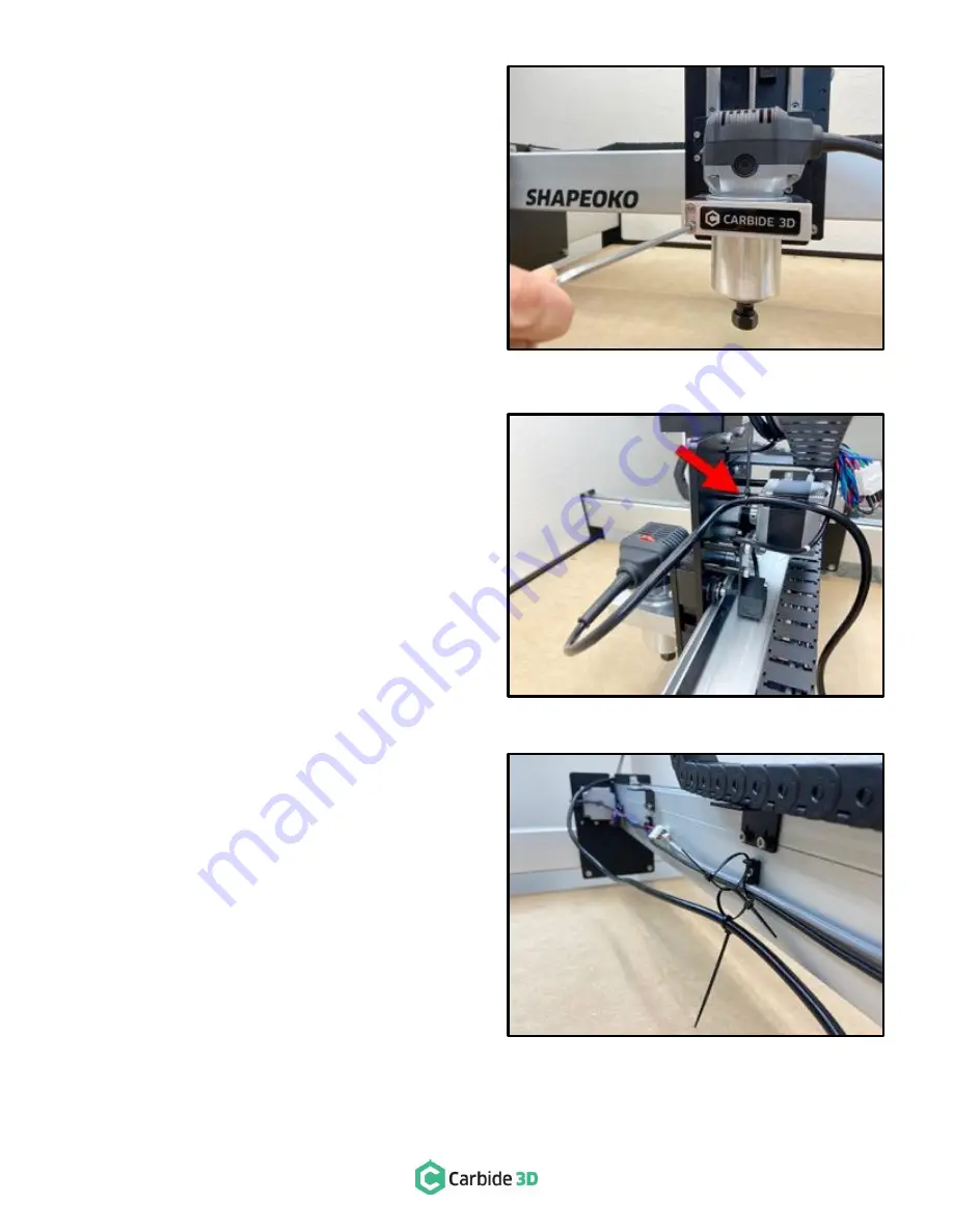
Use the 4mm hex key to secure the compact
router by tightening the two (2) M5x55mm socket
head cap screws on the front of the router mount
as shown in
Figure 10
-
5
.
Secure the Router Power Cable
The power cord routes back through the drag chain,
loosely snakes along the back of the X-rail, then up and
over the Y2-carriage. Cable ties are used to secure it in
place.
1.
Loop the router cable behind the Z-Plus as shown
in
Figure 10
-
6
.
2.
Use one (1) cable tie to secure the power cord to
the TOP-RIGHT X-motor standoff at the back of
the Z-Plus. See
Figure 10
-
6
.
The router’s power cord can cause electromagnetic
interference (EMI) for the motor extension cables and the
USB cable, so we want to route it as far away from these
cables as possible.
To begin, w
e’re going to create a
two-link cable tie chain,
with each link about 1-inch in diameter.
3.
Collect three (3) cable ties.
4.
Create the first 1-inch loop at the open
attachment point on the center cable tie mount.
Loop the second cable tie through the first, and
create another 1-inch loop. Finally, use a third
cable tie to secure the router power cable to the
cable tie chain. See
Figure 10
-
7
.
5.
Route the power cord through the circular cutout
at the top of the Y2-carriage. See
Figure 10
-
7
.
Figure 10-5
Figure 10-7
Figure 10-6
Summary of Contents for SHAPEOKO XXL
Page 1: ...X X L A S S E MB L Y G U I D E ...
Page 14: ...docs carbide3d com 12 Figure 2 2 Step 2 Baseframe ...
Page 20: ...docs carbide3d com 18 Figure 3 2 Step 3 Carriages ...
Page 29: ...support carbide3d com 27 Figure 4 2 Step 4 Gantry ...
Page 34: ...docs carbide3d com 32 Figure 5 2 Step 5 Belting ...
Page 40: ...docs carbide3d com 38 Figure 6 2 Step 6 Drag Chains ...
Page 48: ...docs carbide3d com 46 Figure 7 2 Step 7 Proximity Switches ...
Page 52: ...docs carbide3d com 50 Figure 8 2 Step 8 Wiring ...
Page 57: ...support carbide3d com 55 Figure 9 2 Step 9 Cleanup ...
Page 60: ...docs carbide3d com 58 Figure 10 2 Step 10 Compact Router ...


