21
Open the V-Wheels
1.
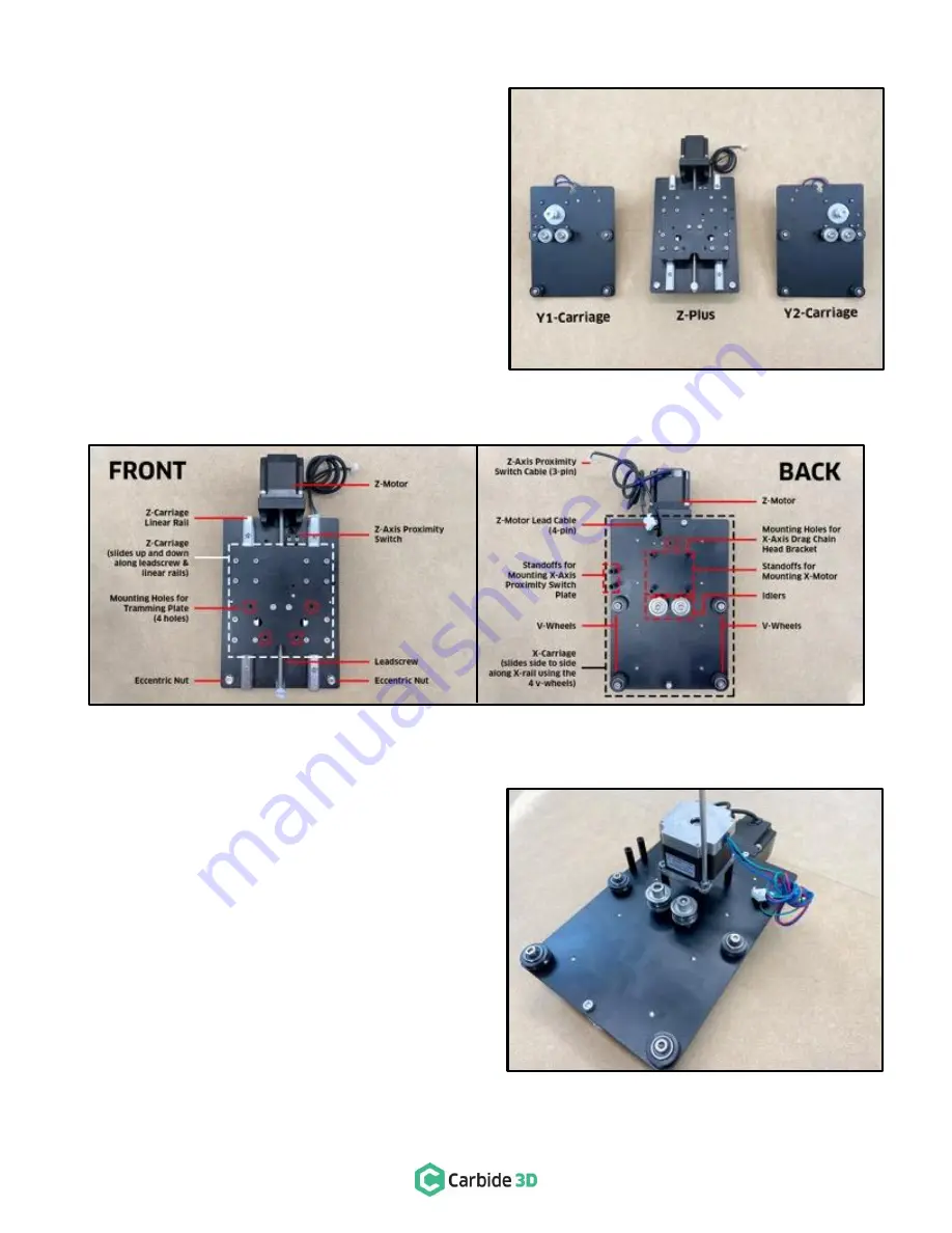
Gather the three (3) carriages (see
Figure 3-6
):
a.
Y-Axis Left Carriage (Y1-carriage)
b.
X/Z-Axis Carriage (Z-Plus)
c.
Y-Axis Right Carriage (Y2-carriage)
At the bottom of each carriage are two (2) eccentric nuts
securing two (2) V-wheels.
2.
Use the 10mm wrench to turn each HD eccentric
nut CLOCKWISE until the dimple is facing up. Refer
back to
Figure 3-4
if needed.
Assemble the Z-Plus
Attaching the X-Motor
Take a minute to familiarize yourself with the features and
layout of the Z-Plus. See
Figure 3-7
.
1.
Place the Z-Plus face down, with the six (6)
pre-installed 30mm standoffs pointing up.
2.
Set the X-motor onto the four (4) evenly spaced
30mm standoffs in the center of the Z-Plus
between the Z-motor and the idlers with the
Carbide
3D label facing down (toward the idlers).
See
Figure 3-8
.
3.
Use the 4mm hex key and four (4) M5x10mm
socket head cap screws to secure the X-motor to
the Z-Plus.
Figure 3-6
Figure 3-7
Figure 3-8
Summary of Contents for SHAPEOKO XXL
Page 1: ...X X L A S S E MB L Y G U I D E ...
Page 14: ...docs carbide3d com 12 Figure 2 2 Step 2 Baseframe ...
Page 20: ...docs carbide3d com 18 Figure 3 2 Step 3 Carriages ...
Page 29: ...support carbide3d com 27 Figure 4 2 Step 4 Gantry ...
Page 34: ...docs carbide3d com 32 Figure 5 2 Step 5 Belting ...
Page 40: ...docs carbide3d com 38 Figure 6 2 Step 6 Drag Chains ...
Page 48: ...docs carbide3d com 46 Figure 7 2 Step 7 Proximity Switches ...
Page 52: ...docs carbide3d com 50 Figure 8 2 Step 8 Wiring ...
Page 57: ...support carbide3d com 55 Figure 9 2 Step 9 Cleanup ...
Page 60: ...docs carbide3d com 58 Figure 10 2 Step 10 Compact Router ...


