CHAPTER 3 EXPOSURE SYSTEM
COPYRIGHT © 1999 CANON INC. CANON PC800s/900s REV.0 AUG. 1999 PRINTED IN JAPAN (IMPRIME AU JAPON)
3-4
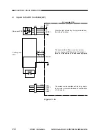
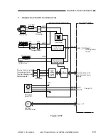
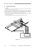
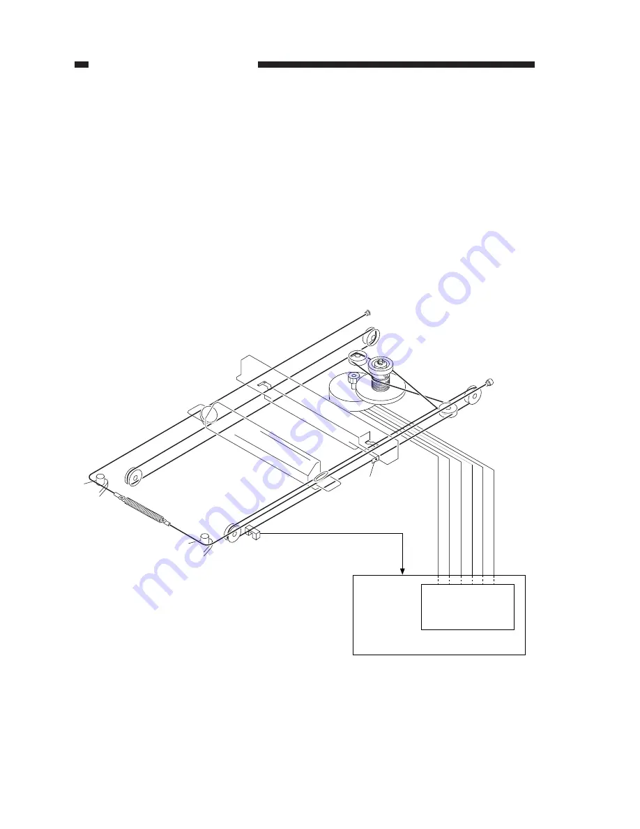
Figure 3-104
J101-1
M2
PS1 Light-blocking
plate
Scanner home position signal (SCHP)
Scanner home position sensor (PS1)
J110-1
SC_COM
-2
SC_B*
-3
SC_B
-4
SC_COM
-5
SC_A*
-6
SC_A
Q109
Motor driver circuit
DC controller PCB
D.
Scanner Drive System
1.
Outline
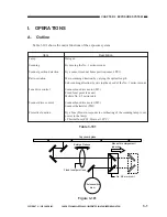
The scanner is driven by the scanner/lens drive motor (M2), whose direction of rotation
changes to move the scanner forward or in reverse.
When moving the scanner forward, the speed of rotation of the motor varies according to the
selected reproduction ratio on a continuous basis; when moving the scanner in reverse, on the other
hand, its speed remains the same regardless of the selected reproduction ratio in normal copying
(312mm/sec, about 3.3 as fast as when moving the scanner forward in Direct).
The distance over which the scanner is moved varies according to the length of copy paper and
the selected reproduction ratio.
The scanner/lens drive motor dives the lens drive system as well as the scanner.
Summary of Contents for PC920
Page 12: ......
Page 34: ......
Page 36: ......
Page 48: ......
Page 50: ......
Page 92: ......
Page 94: ......
Page 122: ......
Page 124: ......
Page 162: ......
Page 164: ......
Page 180: ......
Page 206: ......
Page 240: ......
Page 242: ......
Page 256: ......
Page 263: ......
Page 265: ......
Page 355: ......
Page 383: ......

