CHAPTER 11 TROUBLESHOOTING
COPYRIGHT © 1999 CANON INC. CANON PC800s/900s REV.0 AUG. 1999 PRINTED IN JAPAN (IMPRIME AU JAPON)
11-41
C.
Electrical
1.
After Replacing the Major Parts
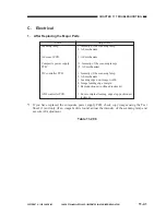
*1: If you have replaced the composite power supply PCB, check copy images using the Test
Sheet; if (and only if) an image fault is found, adjust the intensity of the scanning lamp and
execute AE adjustment.
Table 11-206
Adjustment
1. Intensity of the scanning lamp
2. AE mechanism
1. AE mechanism
(1. Intensity of the scanning lamp)
(2. AE mechanism)
1. Intensity of the scanning lamp
2. AE mechanism
3. Leading edge non-image width
4. Image leading edge margin
5. Reproduction ratio (fine adjustment)
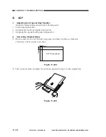
1. Excute original leading edge stop position ad-
justment
Parts
Scanning lamp
AE sensor PCB
Composite power supply
PCB
*1
DC controller PCB
ADF controller PCB
Summary of Contents for PC920
Page 12: ......
Page 34: ......
Page 36: ......
Page 48: ......
Page 50: ......
Page 92: ......
Page 94: ......
Page 122: ......
Page 124: ......
Page 162: ......
Page 164: ......
Page 180: ......
Page 206: ......
Page 240: ......
Page 242: ......
Page 256: ......
Page 263: ......
Page 265: ......
Page 355: ......
Page 383: ......

