CHAPTER 8 ADF
COPYRIGHT © 1999 CANON INC. CANON PC800s/900s REV.0 AUG. 1999 PRINTED IN JAPAN (IMPRIME AU JAPON)
8-15
H.
Controlling the Belt Motor
1.
Outline
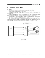
Figure 8-122 is a diagram showing the control circuit for the belt motor (M2).
The belt motor is a 4-phase control stepping motor.
The CPU (Q1) on the ADF controller PCB sends control pulse signals (A, A*, B, B*) to the
motor driver (Q4).
In response, the motor driver changes the output timing of the pulse signals (MA, MA*, MB,
MB*) used for driving the motor to rotate the belt motor clockwise or counterclockwise.
The motor driver is equipped with a limiter function used to keep the motor supplied with a
specific current so that current greater than specified will not flow.
If loads large enough to activate the limiter function occur in succession, the belt motor cannot
rotate as specified, possibly leading to feeding faults. Any feeding fault will cause the ADF con-
troller to flash the Jam indicator on the controller and stop the belt motor at the same time.
Figure 8-122
+24V
Q1
CPU
M1
A
A*
B
B*
MA
MA*
MB
MB*
ADF controller PCB
Q4
Motor
driver
Belt motor
Summary of Contents for PC920
Page 12: ......
Page 34: ......
Page 36: ......
Page 48: ......
Page 50: ......
Page 92: ......
Page 94: ......
Page 122: ......
Page 124: ......
Page 162: ......
Page 164: ......
Page 180: ......
Page 206: ......
Page 240: ......
Page 242: ......
Page 256: ......
Page 263: ......
Page 265: ......
Page 355: ......
Page 383: ......

