CHAPTER 7 EXTERNALS/AUXILIARY MECHANISMS
COPYRIGHT © 1999 CANON INC. CANON PC800s/900s REV.0 AUG. 1999 PRINTED IN JAPAN (IMPRIME AU JAPON)
7-19
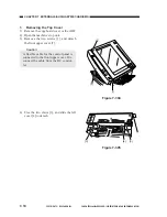
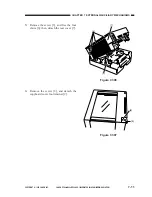
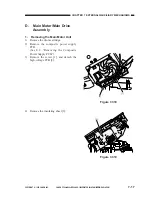
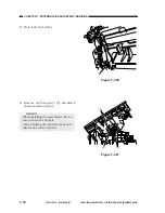
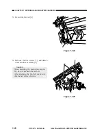
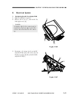
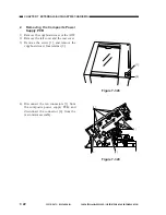
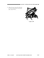
Figure 7-322
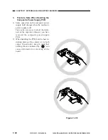
Figure 7-323
[1]
[2]
[3]
2.
Removing the Main Drive Assem-
bly
1) Remove the drum cartridge.
2) Remove the composite power supply
PCB.
(See E.2. “Removing the Composite
Power Supply PCB.”)
3) Remove the screw [1], and detach the
high-voltage PCB [2].
4) Remove the insulating sheet [3].
Summary of Contents for PC920
Page 12: ......
Page 34: ......
Page 36: ......
Page 48: ......
Page 50: ......
Page 92: ......
Page 94: ......
Page 122: ......
Page 124: ......
Page 162: ......
Page 164: ......
Page 180: ......
Page 206: ......
Page 240: ......
Page 242: ......
Page 256: ......
Page 263: ......
Page 265: ......
Page 355: ......
Page 383: ......

