


B. Laser Control Circuit
1. Outline
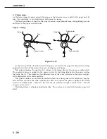
Figure 2-3-2
The CPU controls the following four modes: standby, APC emitting, masking and unmasking.
They are controlled by the LASER CONTROL signals (CNT0, CNT1) sent to the laser driver
(IC801) on the laser driver PCB.
When both CNT0 and CNT1 signals are "L", the laser driver enters the standby mode to reset
the laser driver PCB.
When CNT0 and CNT1 signals are "L" and "H" respectively, the laser driver enters the APC
emitting mode to make the laser diode emit the laser beam. The laser driver also performs the
Auto Power Control, stated in the following section.
When both CNT0 and CNT1 signals are "H", the laser driver enters the masking mode.
Regardless the VIDEO signals (VDO, /VDO), the laser driver prohibits the laser diode from emit-
ting the laser beam.
When CNT0 and CNT1 signals are "H" and "L" respectively, the laser driver enters the
unmasking mode to turn the laser ON/OFF according to the VDO, /VDO signals from the inter-
face controller.
CHAPTER 2
2 - 17
IC201
PD
LD
IC801
J208F-6
J801F-7
CPU
VDO
J201-7
/VDO
J201-8
J208F-9
CNT0
J208F-7
J801F-6
J208F-9
J801F-4
CNT1
J801F-2
/BDI
+3.3V
J208F-12
J801F-1
+5V
J208F-8
J801F-5
J208F-11
J801F-3
C803
J208F-5
J801F-8
Engine controller PCB
Laser driver PCB
(photodiode)
(laser diode)
BD sensor
Comparator
Sample
hold
circuit
Drive
circuit
Logic
circuit


