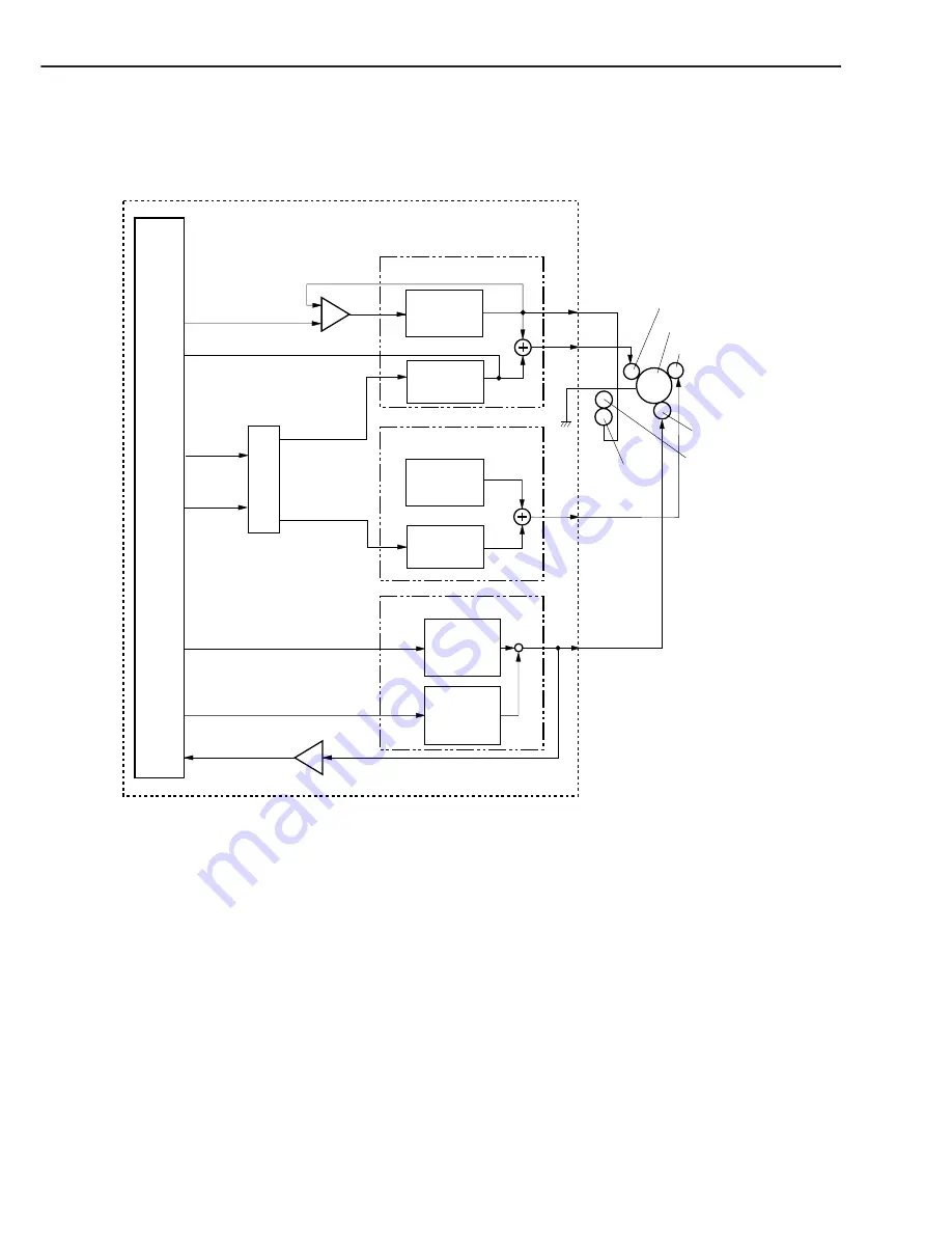
C. High-voltage Power Supply Circuit
1. Outline
Figure 2-2-5
This circuit applies the combined voltage of the DC voltage and AC voltage to the primary charg-
ing roller and developing cylinder, and also applies the positive or negative DC voltage to the
transfer charging roller, according to the instructions sent from the microcomputer (CPU) on the
engine controller.
The circuit adjusts the image density by changing the primary high-voltage (DC) and the
developing bias according to the image density data sent from the interface controller.
CHAPTER 2
2 - 10
Photosensitive drum
CPU
PR
TR
DV
J301
J302
J304
J303
IC201
DVACC
TRNFOT
TRCRNT
TRPWM
Power operational amplifier
PRACC
PRDCC
IC302
IC302
Primary high voltage circuit
CRGSNS
31
30
29
28
32
33
37
DC voltage
generation
circuit
AC voltage
generation
circuit
Developing bias circuit
DC voltage
generation
circuit
AC voltage
generation
circuit
Combined
Combined
Transfer voltage circuit
Positive
voltage
generation
circuit
Negative
voltage
generation
circuit
Primary charging roller
Developing cylinder
Transfer
charging roller
Engine controller PCB
J305
FG
Pressure roller
Fixing film unit


