background image

Chapter 18

18-17

F-18-32

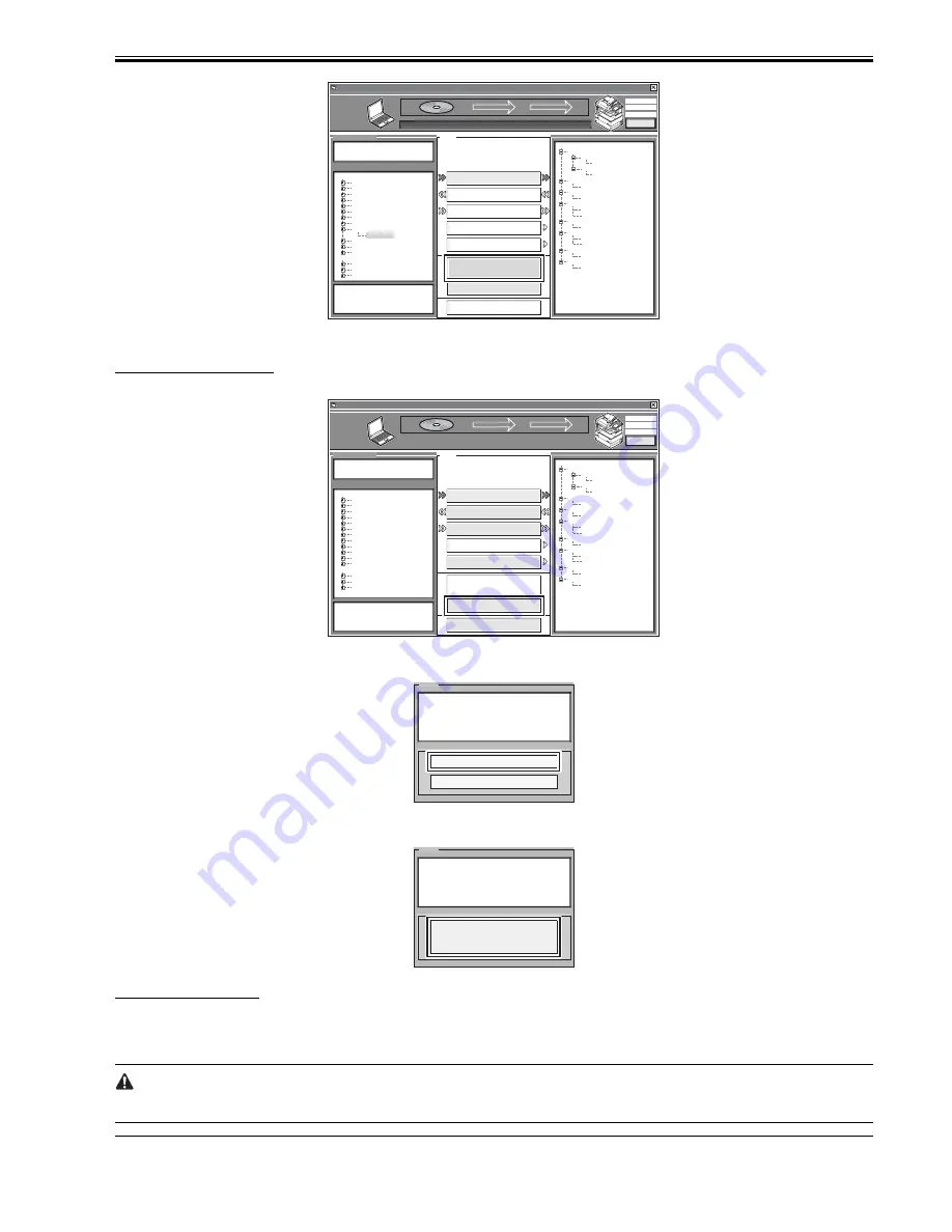
5) Start up the machine. The subsequent procedure differs depending on the download mode.

If the machine is in normal mode,

5-1) Click [Shutdown].

F-18-33

5-2) Click [Start Shutdown] so that the machine starts the shut-down sequence.

F-18-34

5-3) Click [OK], and turn off and then back on the machine's main power switch.

F-18-35

If the machine is in safe mode,

5-1) Turn off and then back on the machine's main power switch.

6) When the machine starts up, it will write the system software to its HDD and flash ROM while showing the progress of writing on the control panel screen. When

done, it will indicate a message asking you to turn off and then back on the power. In response, turn off and then back on the main power.

 Turning Off the Power

Do not turn off the machine's power while downloading or writing is under way; otherwise, the machine may fail to start up. If such is the case, execute HDD

formatting, and download the system software once again.

MEMO:

SelectableFirmware

SelectableFir mware

Control

172.16.1.100
iRC3380
NORMAL

SYSTEM

Firmware Version

Active

USenXXXXn

Hold

USenXXXXi

RCON

XXxxXXXX

DCON

XXxxXXXX

MEAPCONT

XXxxXXXX

G3FAX

XXxxXXXX

BOOTROM

XXxxXXXXC

RUI

XXjaXXXX
XXenXXXX

LANGUAGE

XXjaXXXX
XXenXXXX

D ow n l o a d i n g   c o m p l e t e

ServiceSupportTool DLM10 (Ver.3.22E)

C l e a r

C l i c k   t h e   b u t t o n   o f   t h e   t a s k   t o   b e
exe c u t e d .

Download Firmware

Upload Data

Download Data

Restore Backup System

Format HDD

Return to Main Menu

Shutdown

O       K

BOOT

iRC3380

BROWSER
DCON

HDFormat

iRCXXXX

KEY
SDICT

G3FAX
HELP
LANGUAGE
MEAPCONT
RUI

TTS
WebDAV

SYSTEM

TSTMP

USenvXXXX

SelectableFirmware

SelectableFir mware

Control

172.16.1.100
iRC3380
NORMAL

SYSTEM

Firmware Version

Active

USenXXXXn

Hold

USenXXXXi

RCON

XXxxXXXX

DCON

XXxxXXXX

MEAPCONT

XXxxXXXX

G3FAX

XXxxXXXX

BOOTROM

XXxxXXXXC

RUI

XXjaXXXX
XXenXXXX

LANGUAGE

XXjaXXXX
XXenXXXX

ServiceSupportTool DLM10 (Ver.3.22E)

C l e a r

C l i c k   t h e   b u t t o n   o f   t h e   t a s k   t o   b e
exe c u t e d .

Download Firmware

Upload Data

Download Data

Restore Backup System

Format HDD

Shutdown

S e l e c t   t h e   f i r m wa r e   t o   b e
d ow n l o a d e d .  t h e n   c l i ck   t h e   [ S t a r t ]
bu t t o n .

Return to Main Menu

Start

BOOT

iRC3380

BROWSER
DCON

HDFormat

iRCXXXX

KEY
SDICT

G3FAX
HELP
LANGUAGE
MEAPCONT
RUI

TTS
WebDAV

SYSTEM
TSTMP

Message

Start Shutdown

Cancel

Have you finished downloading and want to
star t shutdown sequence for restar ting
machine ?

Message

Follow the instructions shown on the machine
for shutdown process.
Click [OK] button to return to Main Menu.

O     K

Summary of Contents for iR C2880 series

Page 1: ...Aug 29 2006 Service Manual iR C3380 2880 Series ...

Page 2: ......

Page 3: ... need arises In the event of major changes in the contents of this manual over a long or short period Canon will issue a new edition of this manual The following paragraph does not apply to any countries where such provisions are inconsistent with local law Trademarks The product names and company names used in this manual are the registered trademarks of the individual companies Copyright This ma...

Page 4: ...quiring care to avoid combustion fire Indicates an item prohibiting disassembly to avoid electric shocks or problems Indicates an item requiring disconnection of the power plug from the electric outlet Indicates an item intended to provide notes assisting the understanding of the topic in question Indicates an item of reference assisting the understanding of the topic in question Provides a descri...

Page 5: ...sed to indicate Low The voltage value how ever differs from circuit to circuit In addition the asterisk as in DRMD indicates that the DRMD signal goes on when 0 In practically all cases the internal mechanisms of a microprocessor cannot be checked in the field Therefore the operations of the microprocessors used in the machines are not discussed they are explained in terms of from sensors to the i...

Page 6: ......

Page 7: ...1 2 2 1 Common Settings 1 10 1 2 2 2 Timer Settings 1 12 1 2 2 3 Adjustment Cleaning 1 12 1 2 2 4 Report Settings 1 12 1 2 2 5 System Settings 1 13 1 2 2 6 Copy Settings 1 15 1 2 2 7 Communications Settings 1 15 1 2 2 8 Mail Box Settings 1 16 1 2 2 9 Address Book Settings 1 16 1 2 3 User Maintenance 1 17 1 2 3 1 Cleaning 1 17 1 2 3 2 Inspection 1 20 1 2 4 Safety 1 21 1 2 4 1 Laser safety 1 21 1 2 ...

Page 8: ...ader 2 18 2 8 1 Checking the Contents 2 18 2 8 2 Turning Off the Host Machine 2 19 2 8 3 Installation Procedure 2 19 2 8 4 Installation Procedure in the imageWARE Accounting Manager hereinafter referred to iWAM Environment 2 22 2 9 Installing the Original Tray 2 23 2 9 1 Checking the Content 2 23 2 9 2 Installation Procedure 2 23 2 10 Installing the Key Switch Unit 2 25 2 10 1 Checking the Content...

Page 9: ...e of Operations for a Print Job mono color 3 4 Chapter 4 Main Controller 4 1 Construction 4 1 4 1 1 Construction and Functions 4 1 4 2 Construction of the Electrical Circuitry 4 2 4 2 1 Main Controller PCB main 4 2 4 2 2 SRAM PCB 4 2 4 3 Start Up Sequence 4 3 4 3 1 Overview 4 3 4 3 2 Start Up Sequence 4 3 4 4 Actions when HDD Error 4 5 4 4 1 E602 in Detail 4 5 4 5 Image Processing 4 7 4 5 1 Overvi...

Page 10: ...OM PCB 4 17 4 7 9 2 Removing the Boot ROM PCB 4 17 4 7 10 Image Memory SDRAM 4 17 4 7 10 1 Before Removing the Image Memory SDRAM PCB 4 17 4 7 10 2 Removing the Image Memory SDRAM PCB 4 18 4 7 11 HDD 4 18 4 7 11 1 Before Removing the HDD 4 18 4 7 11 2 Removing the HDD 4 18 4 7 11 3 When Replacing the HDD 4 18 4 7 12 Controller Fan 4 19 4 7 12 1 Before Removing the Controller Fan 4 19 4 7 12 2 Remo...

Page 11: ... PCB 5 19 5 4 3 Inverter PCB 5 20 5 4 3 1 Before Removing the Inverter PCB 5 20 5 4 3 2 Removing the Inverter PCB 5 20 5 4 4 Scanner Motor 5 21 5 4 4 1 Before Removing the Scanner Motor 5 21 5 4 4 2 Removing the Scanner Motor 5 21 5 4 5 Contact Sensor 5 21 5 4 5 1 Before Removing the Contact Image Sensor CIS 5 21 5 4 5 2 Removing the Contact Image Sensor CIS 5 21 5 4 5 3 After Replacing the CIS 5 ...

Page 12: ... 10 7 2 3 Generation of the Developing Bias 7 10 7 2 4 Generation of the Primary Transfer Bias 7 11 7 2 5 Generation of the Secondary Transfer Bias 7 11 7 3 Image Stabilization Control 7 11 7 3 1 Overview of Image Stabilization 7 11 7 3 2 Timing of Image Stabilization Control 7 12 7 3 3 Drum Film Thickness Detection 7 12 7 3 4 ATR Control 7 13 7 3 5 D max Control 7 14 7 3 6 PASCAL Control 7 17 7 3...

Page 13: ...oving the Transfer Cleaner Unit 7 44 7 9 8 Secondary Transfer External Roller 7 45 7 9 8 1 Removing the Secondary Transfer Outer Roller 7 45 7 9 8 2 After Replacing the Secondary Transfer Roller 7 45 Chapter 8 Pickup Feeding System 8 1 Construction 8 1 8 1 1 Specifications Controls and Functions 8 1 8 1 2 Division into Blocks 8 2 8 1 3 Arrangement of Rollers 8 3 8 1 4 Diagram of Paper Paths w copy...

Page 14: ...pecifying the Delivery Point 8 31 8 11 Parts Replacement Procedure 8 32 8 11 1 Pickup Unit 1 8 32 8 11 1 1 Before Removing the Cassette Pickup Unit 1 8 32 8 11 1 2 Removing the Cassette Pickup Unit 1 8 32 8 11 2 Pickup Unit 2 8 32 8 11 2 1 Before Removing the Cassette Pickup Unit 2 8 32 8 11 2 2 Removing the Cassette Pickup Unit 2 8 32 8 11 3 Sensor Mounting Plate 8 32 8 11 3 1 Before Removing the...

Page 15: ...oving Manual Feed Unit 8 38 8 11 19 Manual Pickup Roller 8 38 8 11 19 1 Before Removing Manual Feed Pickup Roller 8 38 8 11 19 2 Removing Manual Feed Pickup Roller 8 38 8 11 20 Manual Feed Separation Pad 8 39 8 11 20 1 Before Removing Manual Feed Separation Pad 8 39 8 11 20 2 Removing Manual Feed Pickup Separation Pad 8 39 8 11 21 Registration Motor 8 39 8 11 21 1 Before Removing Registration Moto...

Page 16: ... 4 10 4 1 2 Route of Power to the Reader Unit 10 6 10 4 1 3 Timing of Supplying Power to the Reader Unit 10 6 10 4 1 4 Routes of Power to various Options 10 7 10 4 2 Rated Output of DC Power Supply PCB 10 7 10 4 2 1 Rated Output of the Printer Unit Power Supply PCB 10 7 10 4 2 2 Rated Output of the Controller Power Supply PCB 10 7 10 4 2 3 Rated Output of the Options Power Supply PCB 10 8 10 4 2 4...

Page 17: ...e Leakage Breaker 10 23 10 5 11 2 Removing the Electric Leak Breaker 10 23 10 5 12 HV1 PCB 10 23 10 5 12 1 Before Removing the HVT1 PCB for image forming 10 23 10 5 12 2 Removing HVT1 PCB for image forming 10 23 10 5 13 HV2 PCB 10 24 10 5 13 1 Before Removing the HVT2 PCB for transfer 10 24 10 5 13 2 Removing the HVT2 PCB for transfer 10 24 10 5 14 AC Driver PCB 10 25 10 5 14 1 Before Removing the...

Page 18: ...or 10 32 10 5 30 1 Before Removing the Right Cover 10 32 10 5 30 2 Removing the Right Cover 10 32 Chapter 11 MEAP 11 1 MEAP 11 1 11 1 1 Checking the Operating Environment 11 1 11 1 2 Setting Up the Network 11 2 11 1 3 Setting the method to login to SMS 11 3 11 1 4 Login to SMS 11 7 11 1 5 Checking Application List 11 8 11 1 6 Starting and Stopping a MEAP Application 11 9 11 1 7 Checking the Platfo...

Page 19: ...Basic Procedure 13 3 13 3 1 Scheduled Servicing Basic Procedures 13 3 13 3 2 Items of Work for Scheduled Servicing reader unit 13 4 13 3 3 Items of Work for Scheduled Servicing printer unit 13 4 Chapter 14 Standards and Adjustments 14 1 Scanning System 14 1 14 1 1 After Replacing the CIS 14 1 14 1 2 After Replacing the Copyboard Glass 14 1 14 1 3 After Replacing the ADF Reading Glass 14 1 14 1 4 A...

Page 20: ...3 4 Sensor 15 10 15 3 4 1 Sensor Table 15 10 15 3 5 Switch 15 13 15 3 5 1 Switch Table 15 13 15 3 6 Lamps Heaters and Others 15 14 15 3 6 1 Lamp Heaters and Others Table 15 14 15 3 7 PCBs 15 15 15 3 7 1 PCBs Table 15 15 15 3 8 Connectors 15 18 15 3 8 1 Connectors 15 18 15 3 9 Variable Resistors VR Light Emitting Diodes LED and Check Pins by PCB 15 22 15 3 9 1 Variable Resistors VR Light Emiting Di...

Page 21: ...7 5 1 COPIER 17 39 17 5 1 1 COPIER Table 17 39 17 5 2 FEEDER 17 46 17 5 2 1 FEEDER Table 17 46 17 6 OPTION Machine Settings Mode 17 47 17 6 1 COPIER 17 47 17 6 1 1 COPIER Table 17 47 17 6 2 SORTER 17 80 17 6 2 1 SORTER Table 17 80 17 6 3 BOARD 17 80 17 6 3 1 BOARD Table 17 80 17 7 TEST Test Print Mode 17 81 17 7 1 COPIER 17 81 17 7 1 1 COPIER Table 17 81 17 8 COUNTER Counter Mode 17 83 17 8 1 COPI...

Page 22: ...8 19 18 5 1 Outline 18 19 18 5 2 Uploading Procedure 18 19 18 5 3 Downloading Procedure 18 21 18 6 Version Upgrade using USB 18 22 18 6 1 Overview of Menus and Functions 18 22 18 6 2 Points to Note 18 23 18 6 3 Downloading Writing the System Software auto 18 24 18 6 4 Downloading the System Software Confirmation execution when version is downed the same version 18 24 18 6 5 Downloading the System ...

Page 23: ...Chapter 1 Introduction ...

Page 24: ......

Page 25: ...ssories EUR 1 7 1 2 Product Specifications 1 8 1 2 1 Names of Parts 1 8 1 2 1 1 External View 1 8 1 2 1 2 Cross Section 1 9 1 2 2 User Mode Items 1 10 1 2 2 1 Common Settings 1 10 1 2 2 2 Timer Settings 1 12 1 2 2 3 Adjustment Cleaning 1 12 1 2 2 4 Report Settings 1 12 1 2 2 5 System Settings 1 13 1 2 2 6 Copy Settings 1 15 1 2 2 7 Communications Settings 1 15 1 2 2 8 Mail Box Settings 1 16 1 2 2 ...

Page 26: ......

Page 27: ...m configuration 3 for the delivery accessories The configuration is shown in the next section 1 1 2 System Configuration 1 Delivery Accessories 0013 8249 iR C3380i iR C3380 iR C2880i iR C2880 The system configuration is shown below F 1 1 1 Finisher Y1 1a Installation Procedure Mounting the Finisher Y1 Mounting the Buffer Path Unit 4 2 Saddle Finisher Y2 2a Installation Procedure Mounting the Finis...

Page 28: ...Path Unit E2 Function Accessory needed Saddle function Saddle Finisher Y2 Optional Power Supply R1 100V Buffer Path Unit E2 Function Accessory needed Punch function Finisher Y1 or Saddle Finisher Y2 Optional Power Supply R1 100V Buffer Path Unit E2 Puncher Unit L1 M1 N1 P1 1 Finisher Z1 1a Installation Procedure Mounting the Finisher Z1 2 Copy Tray J1 Installation Procedure Refer to this service m...

Page 29: ...ccessories 0013 8333 iR C3380i iR C3380 iR C2880i iR C2880 The system configuration is shown below F 1 3 1 Inner 2 way Tray D1 1a Installation Procedure Mounting the Inner 2 way Tray D1 2 Copy Tray J1 Installation Procedure Refer to this service manual 1a ...

Page 30: ...llation Procedure Refer to this service manual 6 2 Cassette Pedestal Y3 6a Installation Procedure Mounting the 2 Cassette Pedestral Y3 7 Envelope Cassette C2 100V 8 Envelope Cassette Attachment C2 115V 200V 8a Installation Procedure Mounting the Envelop Cassette Attachment C2 9 Optional Power Supply P2 120V 230V as standard equipments It is needed when mounting the Side Paper Deck Z1 4 Installatio...

Page 31: ...80 The following shows a typical system configuration F 1 6 T 1 7 1 1 8 Cassette Heater System Configuration 2 0014 2692 iR C3380i iR C2880i iR C2880 The following shows a typical system configuration 1 Reader Heater Unit B1 Installation Procedure Refer to this service manual 2 Cassette Heater PCB G1 1 Cassette Heater Unit Service parts installation to the printer unit A Heater PCB C1 is needed fo...

Page 32: ...Transmission Accessories EUR 0013 9812 iR C3380i iR C3380 iR C2880i iR C2880 1 Cassette Heater Unit 29 attached to the Cassette Feeding Unit 2 Heater Switch PCB C1 3 Outlet Unit 4 Cassette Heater Attachment D2 1 Cassette Heater Attachment D2 Installation Procedure Refer to this service manual 2 Cassette Heater Unit 23 Its operation requires the installation of the Cassette Heater Attachment D2 1 2...

Page 33: ...12MB Expansion RAM C1 16 HDD Data Encryption Kit B1 17 Coior Network Printer Unit J1 18 Super G3 FAX Board W1 19 Voice Guidance Kit B1 20 Voice Operation Kit A1 Function Accessory needed Overview UFRII Printing Color UFRII Printer Kit Q1 PCL Printing Color UFRII PCL Printer Kit Q1 LIPS PS Printing Color UFRII PCL Printer Kit Q1 Color PS Printer Kit Q1 PDF TIFF JPEG direct printing Direct Printing ...

Page 34: ...Q1 Secured Print Function Encrypted Printing Software C1 iWAMS Function Access Management System Kit A1 1 ADF Reading Glass Retainer 2 DADF 3 Reader Cover front 4 Control Panel 5 Front Right Cover 6 Right Inside Cover 7 Delivery Tray 8 Front Cover 9 Cassette 1 10 Cassette 2 11 Left Cover lower 12 Left Cover 13 Controller Cover 14 Delivery Tray Guide 15 Copyboard Glass 16 Security Key 17 Rear Cover...

Page 35: ...r Cassette 1 20 Pickup Roller Cassette 1 21 Vertical Path Roller 2 22 Cassette 2 Pickup Assembly 23 Feed Roller Cassette 2 24 Separation Roller Cassette 2 25 Pickup Roller Cassette 2 26 Vertical Path Roller 3 27 Cassette 3 Pickup Assembly 28 Feed Roller Cassette 3 29 Separation Roller Cassette 3 30 Pickup Roller Cassette 3 31 Vertical Path Roller 4 32 Cassette 4 Pickup Assembly 33 Feed Roller Cass...

Page 36: ...isplay Settings Initial Functions and Function Order Settings Copy Express Copy Send Mail Box Print Job Scan MEAP No Copy Screen Display Settings Regular Copy Only Regular and Express Copy Express Copy Only Regular Copy Screen Priority On Off Set System Monitor as the Default Screen On Off Set the Default Screen for System Monitor Copy Send Fax Print Receive Device Auto Clear Setting Initial Funct...

Page 37: ...nt Settings No Paper Select All Paper Sources Auto Copies 1 to 9 999 sets Finishing If No Finisher Is Attached or Only the Optional Inner 2way Tray D1 is Attached Do Not Collate Collate Rotate Collate Group Rotate Group If the Optional Finisher Z1 Is Attached Do Not Collate Collate Offset Collate Group Offset Group Staple Corner Top Left Bottom Left Top Right Bottom Right Double Left Right If the ...

Page 38: ...titcher Staple Repositioning 1 Press Start No Saddle Stitch Position Adjustment 1 All paper sizes 2 0 mm to 2 0 mm in 0 25 mm increments 0 00 mm Yes Creep Displacement Correction Adjustment Correction for each paper type 0 000 to 0 078 0 00 mm to 2 00 mm in 0 002 0 05 mm No increments 0 010 0 25 mm Auto Gradation Adjustment Plain Heavy 1 Heavy 2 No Full Adjust Automatic after the machine prints an...

Page 39: ...munications Settings E mail I Fax Settings Yes Maximum Data Size for Sending 0 Off 1 to 99 MB 3 MB Full Mode TX Timeout 1 to 99 hours 24 hours Divided Data RX Timeout 0 to 99 hours 24 hours Default Subject 40 characters maximum Attached Image Print MDN DSN on Receipt On Off Always send notice for RX errors On Off Use Send Via Server On Off Allow MDN Not Via Server On Off Fax Settings 2 Send Start ...

Page 40: ...ng Option Settings Copy Set Num Op On Off Yes ID User Name On Off Date On Off Characters On Off Display Remaining Toner Error Message On Off No Display ID User Name On Off No USB Settings Use USB Device On Off Yes Use USB Host On Off Yes Device Information Delivery Settings Register Destinations Auto Search Register Register Details Erase Print List Auto Delivery Settings Everyday Select Days Off ...

Page 41: ...mission 1 On Off Yes Erase Failed TX On Off Yes Data Compression Ratio High Ratio Normal Low Ratio Yes Handle Documents with Forwarding Errors Always Print Store Print Off Yes Retry Times 1 0 to 5 times 3 times Yes Edit Standard Send Settings Scanning Mode Clr B W 200x200 dpi No File Format TIFF PDF Auto Select Stamp Off Register Favorites Button Register Edit Erase M1 to M18 Display Comment On Of...

Page 42: ... 1 ECM TX On Off Yes Pause Time 1 to 15 seconds 2 seconds Yes Auto Redial On Off Yes Redial Times 1 to 10 times 2 times Redial Interval 2 to 99 minutes 2 minutes TX Error Resend Error and 1st Page All pages Off Check Dial Tone Before Sending On Off Yes Fax Settings RX Settings 1 ECM RX On Off Yes Fax Settings Dual Line Options 1 Unit Telephone 20 digits maximum No Unit Name 24 characters maximum N...

Page 43: ...e of the Platen Cover 1 Clean the platen glass 1 and the underside of the platen cover 2 with a cloth moistened with water or solution of mild detergent well wrung then dry wipe them with a soft dry cloth F 1 13 2 Feeder 1 Open the feeder cover F 1 14 2 Clean the 3 rollers 1 on the underside of the feeder cover with a cloth moistened with water well wrung then dry wipe them with a soft dry cloth F...

Page 44: ...h water well wrung then dry wipe them with a soft dry cloth F 1 18 6 Close the middle cover and the feeder cover 3 Original Reading Block 1 Open the feeder F 1 19 2 Clean the original reading block 1 with a cloth moistened with water well wrung then dry wipe them with a soft dry cloth F 1 20 3 Clean the side part of the rubber roller 1 with a cloth moistened with water well wrung then dry wipe the...

Page 45: ...ning tool 1 from the backside of the front cover F 1 23 3 Hold the knob of the cleaning tool 1 and slowly move it back and forth to clean the 4 internal points 2 of the host machine with the pad at the tip of the cleaning tool F 1 24 4 Return the cleaning tool to the underside of the front cover and close the front cover 1 1 1 1 2 ...

Page 46: ...about once a month and keep a record of inspection Go through the following 1 Turn off the main power switch 2 Push the test button 1 of the breaker with the tip of a ball point pen or the like F 1 25 3 Check to see that the breaker switch 1 shifts to the OFF side F 1 26 4 Shift the breaker switch 1 back to the ON side F 1 27 Check to be sure that the breaker switch is on the ON side If it has sto...

Page 47: ...on put into force regulations concerning laser products on August 2 1976 These regulations apply to laser products manufactured on and after August 1 1976 and the sale of laser products not certified under the regulations is banned within the Untied States The label shown here indicates compliance with the CDRH regulations and its attachment is required on all laser products that are soled in the ...

Page 48: ...RISK OF EXPLOSION IF BATTERY IS REPLACED BY AN INCORRECT TYPE DISPOSE OF USED BATTERIES ACCORDING TO THE INSTRUCTIONS The following warnings are given to comply with Safety Principles EN60950 Wenn mit dem falschen Typ ausgewechselt besteht Explosionsgefahr Gebrauchte Batterien gemäß der Anleitung beseitigen 1 2 5 Product Specifications 1 2 5 1 Type and function 0013 8329 iR C3380i iR C3380 iR C288...

Page 49: ...sensor Cassette capacity 680 sheets 64g m2 paper 550 sheets 80g m2 paper Multifeeder tray capacity 55 sheets 64g m2 paper 50 sheets 80g m2 paper Non image width leading edge 4 0 1 5 1 0mm one side both sides Non image width left right 2 5 1 5mm one side both sides Image margin leading edge 4 0 1 5 1 0mm Image margin left right 2 5 1 5mm double sided 2 5 2 0mm Image margin trailing edge 2 5mm Energ...

Page 50: ...rd Heavy paper 2 up to 164g m2 A4 LTR B5 12 5 A4R LTRR 8 5 B4 LGL 8 5 A3 7 5 LDR 7 0 SRA3 7 0 12 X18 7 0 A5R B5R STMTR 6 to 2 A5 LTR 12 5 OHP Color 5 5 BK 20 20 1200dpi A4 LTR 16 5 15 12 5 16 5 15 16 5 15 12 5 16 5 15 A4R LTRR 8 5 8 5 8 5 8 5 8 5 8 5 B4 LGL 8 5 8 5 8 5 8 5 8 5 8 5 A3 7 5 7 5 7 5 7 5 7 5 5 0 LDR 7 0 7 0 7 0 7 0 7 0 5 0 SRA3 7 0 12 X18 7 0 7 0 7 0 A5R STMTR 6 5 6 5 6 5 6 5 6 5 6 5 C...

Page 51: ... OHP A4 LTR Yes No Yes Card Postal card A6R non fixed size Return postal card A5 A5R non fixed size No No Yes Four panel postcard A4 A4R non fixed size No No Yes Label A4 A4R LTR LTRR No No Yes Paper with three holes Same as standard paper Yes Yes Yes Secondary master drawing A3 B4 A4 Yes No Yes Envelope Com10 Monarch DL ISO C5ISO B5 yogata NO 4 Yes No Yes ...

Page 52: ......

Page 53: ...Chapter 2 Installation ...

Page 54: ......

Page 55: ...4 2 4 1 Troubleshooting the Network 2 14 2 4 2 Making Checks Using a Loopback Address 2 15 2 4 3 Making a Check Using a Local Host Address 2 15 2 5 Checking the Images Operations 2 15 2 5 1 Checking the Images 2 15 2 6 Relocating the Machine 2 16 2 6 1 Relocating the Machine 2 16 2 7 Installing the Copy Tray 2 16 2 7 1 Checking the Components 2 16 2 7 2 Turning Off the Machine 2 16 2 7 3 Installat...

Page 56: ...ation Procedure 2 41 2 14 Installing the Voice Operation Kit 2 47 2 14 1 Checking the Contents 2 47 2 14 2 Turning Off the Host Machine 2 48 2 14 3 Installation Procedure 2 48 2 15 Installing the Power Supply 2 54 2 15 1 Turning Off the Machine 2 54 2 15 2 Installation Procedure 2 55 2 16 Installing the DADF 2 59 2 16 1 Checking the Contents 2 59 2 16 2 Turning Off the Machine 2 60 2 16 3 Installa...

Page 57: ... satisfied C C zone Copying operation is performed normally without any safety issues malfunction and errors in display 3 The machine must not be installed near a source of fire or in an area subject to dust or ammonium gas If the area is exposed to direct rays of the sun provide curtains to the window 4 The room must be well ventilated The level of ozone generated by the machine in use will not a...

Page 58: ... object brought in from a cold to warm place i e as the result of the rapid cooling of the moisture vapor around the object 2 The machine weighs a maximum of about 125 kg including a DADF Be sure to work in a group of 4 persons when lifting it Also lift the main body while keeping it level 2 1 3 Combination Table of Accessories 0014 5103 iR C3380i iR C3380 iR C2880i iR C2880 The following table sh...

Page 59: ...s Internal Revenue Stamps cancelled or uncancelled Cheques or drafts drawn by Governmental agencies Licences and Registrations documents for motor vehicles Also all literary musical artistic and typographical works are copyrighted Whilst certain reproduction of copyright work may be permitted for fair dealing eg for research private study or for the purpose of criticism or review generally reprodu...

Page 60: ...1 left right and lift the machine off the skid 2 The machine weighs a maximum of about 125 kg including a DADF Be sure to work in a group of 4 persons when lifting it Also lift the main body while keeping it level F 2 6 3 Remove all the tapes from the main body 2 2 3 Installation of the Scanner 0013 8246 iR C3380i iR C3380 iR C2880i iR C2880 1 Open the copyboard or the DADF to remove the copyboard...

Page 61: ...t so it may scratch the ITB belt F 2 12 7 Press the push button 1 and hold the grip 2 to open the ITB unit 3 upward F 2 13 8 Secure the ITB unit 1 in place with the tip resistant arm 2 Secure in the lower slot of the 2 Do not touch the ITB If the ITB is scratched it may cause the pickup fault or degradation of the print quality In case the print quality is degraded due to touching the ITB clean th...

Page 62: ... hands as shown in the figure and shake it up and down 5 times to ensure the developer inside spread evenly F 2 18 11 Hold down the drum cartridge as shown in the figure and draw the sealing tape 1 in the direction shown by the arrow F 2 19 12 Hold the drum cartridge as shown in the figure below to set to the specified position of the ITB unit Do not press the drum area over the drum protection co...

Page 63: ...is not opened properly Therefore toner does not get into the drum cartridge from the hopper assembly and the spilled toner strays within the machine If removing the drum cartridge while the shutter lever is not at the Unlock position put the cartridge back and shift the shutter lever to the Unlock po sition and then remove the cartridge 15 Release the tip resistant arm 1 and press the 2 sealing ar...

Page 64: ... toner retainer Bk 1 to the host machine and turn the lever 2 in the direction of the arrow to lock F 2 27 3 Set the rest of the toner retainers in the same way 4 Close the front door 2 2 6 Connection of the Cable 0013 8405 iR C3380i iR C3380 iR C2880i iR C2880 1 Fix the reader communication cable 2 in place with the 3 wire saddles 1 to connect the connector of the both sides to the main body F 2 ...

Page 65: ... is not installed F 2 31 Stamp Model with DADF only 1 Open the DADF feeder cover 1 and separation guide 2 F 2 32 2 Using tweezers fix the stamp in place making sure that the print face of the stamp faces upward Be sure to push in the stamp until a click is felt The presence of a gap can cause paper to jam F 2 33 Size Label only if w DADF 1 Match the side guide rear 1 against the index A4 A3 or LTR...

Page 66: ...at shipment A label in English is attached at shipment F 2 39 2 2 8 Fixing the Machine in Place 0013 8269 iR C3380i iR C3380 iR C2880i iR C2880 If a Cassette Pedestal Is Used 1 Move the machine to its permanent position and fix it in place using the 4 adjusters of the cassette pedestal F 2 40 MEMO No need for adjustment in the case of no cassette pedestal 2 2 9 Setting Up the Cassette 0013 8272 iR...

Page 67: ...e the printout of the test print 2 on the copyboard glass as instructed on the control panel scan 10 Close the copyboard cover DADF 11 Press start to read The machine reads the print out of the test print 2 When a message appears promoting you to remove the test print remove the printout of the test print 2 from the copyboard glass 12 Press test print 3 The machine prints the test print 3 13 Place...

Page 68: ... right cover 2 Adjusting the Margin 2nd side 1 Make a copy using the cassette 1 as the source of paper then check to make sure that the margin on the front side is 2 5 2 0 mm F 2 51 2 If the margin is as indicated change the adjustment value of the horizontal registration for the 2nd side for the cassette 1 COPIER ADJUST FEED ADJ ADJ C1RE An increase by 1 will decrease the margin on the front side...

Page 69: ...n the service label ADJ MFRE 4 Press the Reset key twice to end service mode 5 Adjusting the Margin Along the Leading Edge 1st side Make a copy using the cassette 1 as the source of paper then check to make sure that the margin along the image leading edge L1 is 4 0 1 5 1 0 mm If not make adjustments as follows 1 Make the following selections in service mode COPIER ADJUST FEED ADJ REGIST 2 Change ...

Page 70: ...other hand you need not make a PING based check 1 Make the following selections in service mode COPIER TEST NETWORK PING 2 Enter the IP address using the keypad on the control panel and press the OK key 3 Press the Start key If the PING check is successful the machine will indicate OK otherwise it will indicate NG F 2 58 2 3 3 Making Checks Using a Remote Host Address 0013 8312 iR C3380i iR C3380 ...

Page 71: ...out if the IP address and its settings assigned to the machine is correct b poor connection of the main controller PCB sub LANBAR C check the connectors associated with the main controller PCB sub LANBAR C c faulty main controller PCB sub LANBAR C replace the main controller PCB sub LANBAR C if the machine indicates OK suspect a fault in the user s network environment Report to the system administ...

Page 72: ...t paper on the copyboard glass 3 Remove all toner cartridges and developing assembly so that the developing rotary will not rotate in response to vibration occurring in transit 2 7 Installing the Copy Tray 2 7 1 Checking the Components 0013 9951 iR C3380i iR C3380 iR C2880i iR C2880 F 2 61 2 7 2 Turning Off the Machine 0013 9956 iR C3380i iR C3380 iR C2880i iR C2880 How to Turn Off the Host Machin...

Page 73: ...ay 2 F 2 63 3 Connect the power cable to the outlet 4 Turn on the main power switch 5 Login to the service mode 6 Select the followings to register 1 COPIER OPTION ACC OUT TRAY 7 Check to see the following menu items are added Initial Setting Register Common Specification Setting Delivery Tray Setting 8 Select the copy at the tray B and execute test print 9 Check to see that the copy is delivered ...

Page 74: ...ard reader C1 the card reader mounting kit B1 is necessary Card Reader C1 F 2 64 Card Reader Mounting Kit B1 F 2 65 1 Card reader 1pc 2 Screw RS tightening M4X10 1pc 3 Toothed washer 1pc not used in this machine 1 Card reader base plate 1pc 2 Relay harness 1pc 3 Screw TP M4X25 1pc 4 Screw TP M4X8 1pc 5 Toothed washer 2pc C 1 2 3 1 2 3 4 5 ...

Page 75: ...lation Procedure 0013 8330 iR C3380i iR C3380 iR C2880i iR C2880 After installing the card reader C1 enter the card number to use in the service mode of this machine by selecting the following COPIER FUNCTION INSTALL CARD Unless entering the card number the card fails to be recognized when inserting the card When installing the machine see the Combination Table for Accessory Installation 1 Open th...

Page 76: ...the connector area 2 of the host machine F 2 69 6 Pass the relay cable 2 from the cut off 1 and attach the rear right cover 3 4 screws 4 removed in the step 3 F 2 70 7 Close the cassette upper right cover and the cassette lower right cover 1 2 1 2 1 2 4 3 ...

Page 77: ...x the relay cable 1 of the card reader in place 1 edge saddle 2 1 wire saddle 3 F 2 72 10 Connect the relay cable 1 that is connected in the step 5 with the relay cable 2 of the card reader F 2 73 11 Fit the 2 bosses 1 to attach the card reader 2 1 toothed washer 3 1 screw TP M4X25 4 Take care not to nip the harness 1 2 3 1 2 ...

Page 78: ...ing 1 as the first number in Service Mode COPIER FUNCTION INSTALL CARD 2 Press Reset to exit from Initial Settings Registration 3 Select Initial Settings Registration System Administration Settings Network Settings TCP IP Settings IP Address and make settings of IP Address Gateway Address and Subnet Mask suitable for the user s environment 4 Press Reset to exit from Initial Settings Registration 5...

Page 79: ...iR C2880 When installing the machine see the Combination Table for Accessory Installation 1 Remove the 2 face seals 1 F 2 76 2 Tighten 2 stepped screws RS tightening 1 to the upper right cover of the host machine A In the case that the card reader is not attached to the host machine 1 Document Tray 1pc 2 washer 2pc 3 stepped screw RS tightening 2pc 4 stepped screw M4 2pc do not use with the host m...

Page 80: ...apter 2 2 24 F 2 77 B In the case that the card reader is attached to the host machine F 2 78 3 Set the cut offs 2 of the support plate on the Document Tray 1 with the stepped screws 3 F 2 79 1 1 3 1 2 2 ...

Page 81: ...d disk 1 Hold down the control panel power switch for 3 sec or more 2 Follow the instructions on the shutdown sequence screen to let the main power switch be ready to turn off 3 Turn off the power switch 4 Disconnect the power cables for the power outlet 2 10 3 Installation Procedure 0013 8323 iR C3380i iR C3380 iR C2880i iR C2880 1 Release five wire saddles 1 on the rear upper cover to free two c...

Page 82: ...r cover 1 If the cassette pedestal was installed open also the cassette right lower cover 2 F 2 83 4 Pull out the reader power supply cable 1 5 Detach the right rear cover 2 4 screws 3 F 2 84 6 Remove the key switch bracket 1 1 screw 2 1 2 2 3 1 2 1 2 3 ...

Page 83: ...nect the connector 1 on the main body from the wire saddle 2 to get it out to the rear side of the main body 9 Close the wire saddle F 2 87 10 Fix the key switch bracket 1 1 screw 2 Screw removed in the step 6 F 2 88 11 Connect the connector of the key switch unit to the connector 1 of the main unit 2 1 2 1 3 1 2 2 1 ...

Page 84: ...ed in the step 1 to the wire saddle 18 Connect the power supply cable to the power plug 19 Turn ON the main power switch 2 10 4 Checking After Installation 0013 8325 iR C3380i iR C3380 iR C2880i iR C2880 1 Enter the service mode 2 Select COPIER FUNCTION INSTALL KEY register 1 3 Turn OFF ON the main power switch according to the shutdown sequence 4 Check the display Please set the control key 5 Ins...

Page 85: ...80 iR C2880i iR C2880 Prepare the following parts because each part of the heater PCB is assigned as service part F 2 92 T 2 3 2 11 4 Turning Off the Host Machine 0014 2492 iR C3380i iR C3380 iR C2880i iR C2880 How to Turn Off the Main Power When turning off the main power be sure to go through the following steps to protect the hard disk 1 Hold down the control panel power switch for 3 sec or mor...

Page 86: ...at blade screwdriver detach the connector cover 2 F 2 93 3 Fit the 3 hooks 2 of the heater unit 1 to the slit of the base plate to match the hole positions In the case of mounting the heater unit make sure to check that the 3 hooks 2 are tightly fitted and there is no jiggle F 2 94 4 Mount the heater unit 1 with the screw binding M4X6 2 and connect the connector 3 F 2 95 5 Attach the connector cov...

Page 87: ...k by inserting the part indicated as 1 from the front side of the host machine with a flat blade screwdriver detach the connector cover 2 F 2 97 3 Fit the 3 hooks 2 of the heater unit 1 to the slit of the base plate to match the hole positions In the case of mounting the heater unit make sure to check that the 3 hooks 2 are tightly fitted and there is no jiggle F 2 98 4 Mount the heater unit 1 wit...

Page 88: ... the rear side of the host machine B F 2 100 7 Put back the cassette 3 and 4 2 11 6 Mounting the Heater PCB 0014 2782 iR C3380i iR C3380 iR C2880i iR C2880 1 Open the cassette upper right cover 1 In the case that the cassette pedestal is mounted also open the cassette lower right cover 2 F 2 101 2 Disconnect the reader power cable 1 3 Detach the rear right cover 2 4 screws 3 1 2 ...

Page 89: ... cover 1 lattice connector 2 in the case that the cassette pedestal is mounted 3 screws 3 to loosen 6 screws 4 to remove F 2 104 6 Pull out the 3 harnesses of the AC connector 1 from the cable guides 2 to remove them from the 2 wire saddles 3 7 Remove the harness of the DC connector 5 from the edge saddle 4 1 2 3 1 2 3 4 1 4 2 4 ...

Page 90: ...the heater PCB 2 2 screws TP M3X6 3 F 2 106 9 Connect the AC connector 1 to the heater PCB and pass it through the edge saddle 2 F 2 107 10 Connect the 2 AC connectors 1 to the heater PCB and pass them through the edge saddle 2 3 1 5 4 2 1 2 3 3 1 1 1 2 ...

Page 91: ...pedestal is mounted rear right cover reader power cable 13 In the case that the cassette pedestal is mounted close the cassette lower right cover Close the upper right cover 14 Turn ON the heater switch 2 12 Installing the Cassette Heater for the Cassette Pedestal 2 12 1 Checking the Parts 0014 2733 iR C3380i iR C3380 iR C2880i iR C2880 Prepare the following parts because each part of the Cassette...

Page 92: ...ff 3 Turn off the power switch 4 Disconnect the power cables for the power outlet 2 12 3 Mounting the Cassette Heater Attachment 0014 2970 iR C3380i iR C3380 iR C2880i iR C2880 1 Detach the small cover 2 of the lower rear cover 1 the detached small cover is not used 1 screw 3 2 Detach the lower rear cover 1 lattice connector 4 3 screws 5 to loosen 6 screws 6 to remove No Name Part No Qty 1 Power C...

Page 93: ...t in place with the edge saddle 4 4 Attach the heater outlet 2 with the screw TP M3X6 5 F 2 112 5 Attach the lower rear cover 6 Detach the rear cover 1 of the cassette pedestal 4 screws 2 F 2 113 7 Using nippers cut off the face plate 2 of the rear cover 1 of the cassette pedestal 5 6 1 6 4 6 3 6 2 3 1 5 2 4 1 2 2 ...

Page 94: ...ottom of the cassette pedestal attach it with 2 screws TP M3X6 4 F 2 115 F 2 116 9 Attach the rear cover of the cassette pedestal 10 Connect the lattice connector to the host machine 11 Connect the power code 1 to the power code unit 2 and the environment heater outlet 3 of the host machine 12 Attach the outlet label 4 1 2 1 3 2 4 ...

Page 95: ...3 use the screw that was removed in the step 1 1 screw TP M3X6 4 F 2 118 2 13 Installing the Voice Guidance Kit 2 13 1 Checking the Contents 0014 2056 iR C3380i iR C3380 iR C2880i iR C2880 Voice Guidance Kit B1 F 2 119 1 3 2 4 1 3 4 2 1 2 3 4 5 6 9 8 7 10 14 15 11 12 13 16 17 18 ...

Page 96: ...f 3 Turn off the power switch 4 Disconnect the power cables for the power outlet 1 Speaker Unit Upper 1pc 10 Screw binding M4X6 1pc 2 Speaker Unit Lower 1pc 11 Screw binding M4X40 2pc 3 Cable 1300 mm 1pc 12 Screw binding M3X16 1pc 4 Cable 1850 mm 1pc 13 Screw binding M4X16 1pc 5 Cord Guide 7pc 14 Ferrite Core 1pc Use 2pc in this machine 15 Wire Saddle 1pc 6 Voice Board 1pc 16 Voice Guidance Kit Us...

Page 97: ...stallation Procedure 1 Release five wire saddles 1 on the rear upper cover make two cables 2 coming off upward F 2 120 2 Detach the rear upper cover 1 3 screws 2 to remove 6 screws 3 to loosen F 2 121 3 Detach the controller box cover 1 14 screws 2 Do not make the screws fall off F 2 122 4 Detach the blanking plate 1 Do not use the detached blanking plate 1 2 1 2 2 3 1 2 2 2 2 ...

Page 98: ...ing F 2 125 The slide switch SW1 on the voice operation board is mounted to switch between in accordance with the transfer speed of PCI bus If the position of the switch does not match the transfer speed the voice is not correctly played such as the interruption If you move the switch by mistake be sure to return it to the correct position In this machine the switch should be positioned at 66MHz 1...

Page 99: ...ctor F 2 127 8 Fix the voice board 1 in place with two screws 2 removed in the step 4 F 2 128 9 Attach the cover in the opposite step from the one for detaching controller box cover rear upper cover 10 Fix two cables removed in the step 1 in place with wire saddle 11 Remove the screw 1 and the blanking seal 2 fixed to the right upper cover Do not use the removed screw and blanking seal 33MHz 66MHz...

Page 100: ... F 2 130 13 Mount the speaker unit upper 1 on the speaker unit lower fix them with a screw binding M4X6 2 from beneath F 2 131 14 Detach the cover 1 on the cord guide F 2 132 15 Peel off two released papers on the cord guide 1 affix them to the position on the right side as in the chart 3 2 1 2 3 1 1 2 1 ...

Page 101: ...3 16 Connect the cable 2 into the speaker unit 1 F 2 134 17 Attach the ferrite core 1 to the cable Be sure that the length 2 is 50 mm or shorter F 2 135 18 Connect the cable 1 to the terminal 2 of the voice board 1 1 2 1 2 ...

Page 102: ... Voice Board is displayed that means that the voice board is correctly recognized 2 Setting After Installation To use voice guidance after power on it is necessary to set the followings 1 Select Additional Function System Settings Voice Navigation Management Settings Use Voice Guide 2 Select ON key Default OFF 3 Press OK key 3 Operation Check When Using the Voice Guidance 1 Press the reset key for...

Page 103: ...her 2pc Use 1pc in this machine 16 Wire Saddle 1pc 5 Voice Operation Board 1pc 17 Voice Guidance Kit Users Guide 1pc 6 Board Support Plate 1pc 18 Voice Guidance Kit Users Guide CD 1pc 7 Board Support Plate 1pc 19 Voice Operation Kit Users Guide 1pc 8 Ferrite Core 2pc 20 Voice Operation Kit Users Guide CD 1pc 9 Screw TP M3X6 2pc 21 Voice Operation Quick Guide 1pc 10 Screw binding M4X6 2pc 22 FCC IC...

Page 104: ...ower switch be ready to turn off 3 Turn off the power switch 4 Disconnect the power cables for the power outlet 2 14 3 Installation Procedure 0014 2523 iR C3380i iR C3380 iR C2880i iR C2880 When installing the machine see the Combination Table for Accessory Installation 1 Installation Procedure 1 Release five wire saddles 1 on the rear upper cover make two cables 2 coming off upward F 2 139 2 Deta...

Page 105: ...the board support plate 2 to the voice operation board 1 2 screws TP M3X6 3 2 washers 4 2 hex screws 5 F 2 143 Check the Slide Switch SW1 on the Voice Operation Board The slide switch SW1 on the voice operation board is mounted to switch between in accordance with the transfer speed of PCI bus 1 2 2 2 2 1 2 1 2 3 4 4 5 5 ...

Page 106: ... 66MHz F 2 144 6 Connect the voice operation board 1 to the connector of the main controller PCB When inserting the board into the connector be sure that the board is vertical against the connector F 2 145 7 Fix the voice operation board 1 with two screws 2 removed in the step 4 F 2 146 8 Attach the cover in the opposite step from the one for detaching controller box cover rear upper cover 9 Fix t...

Page 107: ...r unit lower 1 1 screw binding M4X20 2 1 screw binding M3X20 3 F 2 148 12 Mount the speaker unit upper 1 on the speaker unit lower fix them with two screws binding M4X6 2 from beneath F 2 149 13 Detach the cover 1 of the cable guide F 2 150 14 Peel off the released paper of the cable guide 1 affix it to the position on the right side as in the chart 3 2 1 1 2 3 2 1 1 ...

Page 108: ...ore 1 to the cable Be sure that the length 2 is 50 mm Fix it on the opposite side in the same procedure F 2 152 16 Connect the cable 2 to the speaker unit 1 F 2 153 17 Connect another cable 1 to the terminal 2 of the voice operation board 1 1 2 2 1 ...

Page 109: ...ard is recognized Service mode Select COPIER DISPLAY ACC STS PCI If Voice Operation is displayed that means that the voice operation board is correctly recognized 2 Setting After Installation To use voice operation kit after power on it is necessary to set the followings 1 Select Additional Function System Settings Voice Navigation Management Settings Use Voice Navigation 2 Select ON key Default O...

Page 110: ...key or the voice recognition button three seconds or longer 2 15 Installing the Power Supply 2 15 1 Turning Off the Machine 0014 1282 iR C3380i iR C3380 iR C2880i iR C2880 How to Turn Off the Host Machine When turning off the main power be sure to go through the following in strict sequence to protect the machine s hard disk 1 Hold down on the power switch on the control panel for 3 sec or more 2 ...

Page 111: ...ower Supply PCB 1 Open the 4 wire saddles 1 on the upper rear cover and move the cable 2 upward F 2 158 2 Detach the upper rear cover 1 4 screws 2 remove 3 screws 3 loosen F 2 159 3 Detach the lower rear cover 1 6 screws 2 F 2 160 If a Cassette pedestal 3 exists disconnect the lattice connector 4 1 2 1 2 2 3 2 1 2 ...

Page 112: ...sette pedestal 1 is connected remove the stopper 2 then unplug the power code 1 2 screws 3 F 2 162 5 Detach the protection cover 1 1 screw 2 F 2 163 6 Free the harness 2 by picking the reuse band 1 F 2 164 7 Remove the wire saddle 2 that holds the harness 1 4 3 3 1 2 1 2 2 1 ...

Page 113: ... 9 Connect 7 connectors 2 to the optional power supply 1 F 2 167 10 Attach the protection cover 1 Hook 2 claws 2 1 screws the screw removed in step 5 3 F 2 168 2 Mounting Finisher Connector Mount 1 Pull out the cassettes 2 Detach the lower left cover 1 5 screws 2 2 1 2 2 1 2 2 2 1 1 3 2 ...

Page 114: ...ount the finisher connector mount 1 1 screw RS tightening M3X8 2 F 2 171 5 Fix the finisher harness in place with the 2 wire saddle 1 and the edge saddle 2 and connect 2 connectors 3 F 2 172 6 Cut out the blanking plate 1 of the lower left cover with the nippers 2 1 2 1 2 1 2 3 2 1 ...

Page 115: ... outlet 11 Turn ON the switch of the main power 2 16 Installing the DADF 2 16 1 Checking the Contents 0014 1041 iR C3380i iR C3380 iR C2880i iR C2880 DADF L1 F 2 174 1 DADF Main Unit 1pc 2 Blanking Seal 2pc 3 Stamp 1pc 4 Hinge Cover Right 1pc 5 Hinge Cover Left 1pc 6 Stepped Screw M5X6 2pc 7 Stepped Screw M4X10 3pc 8 Self Tapping Screw M3X8 4pc 9 Document Size Label 1pc 10 Glass Cleaning Position ...

Page 116: ... the main power switch may be turned off 3 Turn off the main power switch 4 Disconnect the power cable for the power outlet 2 16 3 Installation Procedure 0014 1044 iR C3380i iR C3380 iR C2880i iR C2880 1 Detach the pressing plate of the main unit attach the blanking seal 1 to the hinge hole F 2 175 2 Remove five screws 1 on the upper side of the unit Do not use these screws F 2 176 3 Tighten two s...

Page 117: ...n them so that DADF is aligned against the left side of the unit when closing DADF F 2 179 F 2 180 6 Open the DADF feeder cover 1 and separation guide 2 F 2 181 7 Attach the stamp 1 using tools such as tweezers Attach the stamp with the stamped surface upside Incomplete fixation of the stamp results in jam Press the stamp until it clicks 1 2 ...

Page 118: ...paration guide and the DADF feeder cover 9 Connect DADF cable 1 F 2 183 2 16 4 Cleaning the Copyboard Glass 0014 1052 iR C3380i iR C3380 iR C2880i iR C2880 1 Wipe DADF reading glass with a cloth moistened with water well wrung F 2 184 1 1 ...

Page 119: ... hinge check 1 3 Left Hinge Height Adjustment 1 Adjust the left hinge with the height adjustment screw 1 Loosen the fixing nut 2 before adjustment Tighten it after adjustment When the front side is fixed incompletely Rotate the adjustment screw clockwise set the front side to the glass When the rear side or both sides are fixed incompletely Rotate the adjustment screw counterclockwise set the rear...

Page 120: ...vice mode 2 Select the screen in the following order to display the adjustment screen 1 FEEDER 2 FUNCTION 3 TRY A4 highlighted 3 Align the tray side guide against the A4 A3 indication 4 Press OK key register the width of A4 5 Press TRY A5R highlighted 6 Align the tray side guide against the A5R indication 7 Press OK key register the width of A5R 8 Press the reset key twice to release the service m...

Page 121: ...the copied paper Check the right angle by reading the difference between A and B dimensions at the edge of the copy If there is a difference between A and B perform adjustment from the step 3 F 2 190 4 Loosen three screws 1 for hinge fixation F 2 191 F 2 192 Right angle 10mm 10mm 10mm 10mm B A Chart feed direction ...

Page 122: ...age and determine the optimum value 6 Reproduction Ratio Adjustment MEMO DADF reproduction ratio adjustment is performed by comparing the stream reading copy image and pressing plate reading copy image because the DADF is for color machine Comparison between stream reading copy image and original is performed at DADF for the previous monochrome machine so perform adjustment taking this difference ...

Page 123: ... is not performed the following problems may occur Incorrect under color density of the stream reading image Wrong detection of solid in the stream reading mode 1 Set paper for user normal use on the copyboard glass close DADF 2 Select the screen from the service mode screen in the following order to display the adjustment screen 1 COPIER 2 FUNCTION 3 CCD 3 Press DF WLVL1 key to highlight 4 Press ...

Page 124: ... the left and right hinge assemblies with two each self tapping screws M3X8 1 Fit the sheet inside the rubber plate outside and fix it F 2 198 2 16 7 Operation Check 0014 1097 iR C3380i iR C3380 iR C2880i iR C2880 1 Check the following operations 1 Set the original to DADF check LED ON OFF 2 Check the single sided two sided copy operations 3 When using FAX mode check the stamp operation for FAX se...

Page 125: ... panel according to the shut down sequence indicated so that the main power switch may be turned off 3 Turn off the main power switch 4 Disconnect the power cable for the power outlet 2 17 3 Installation Procedure 0014 0908 iR C3380i iR C3380 iR C2880i iR C2880 1 Fit the inside delivery tray 1 into the delivery assembly slot 2 then hook it on the rear cover slot 3 to secure it in position F 2 200 ...

Page 126: ... more sec has passed turn ON the main power switch 8 Press the additonal functions key Then check the follow menu added Common settings delivery tray setup 9 Select the tray B to copy and perform test copy 10 Set a tray in compliance with the needs of the user ...

Page 127: ...Chapter 3 Basic Operation ...

Page 128: ......

Page 129: ...nstruction 3 1 3 1 2 Connections Among Major PCBs 3 2 3 2 Basic Sequence 3 3 3 2 1 Basic Sequence of Operations at Power On 3 3 3 2 2 Basic Sequence of Operations for a Print Job full color 3 3 3 2 3 Basic Sequence of Operations for a Print Job mono color 3 4 ...

Page 130: ......

Page 131: ...ickup feed system block For detailed discussions of individual functions see the chapters that follow F 3 1 A General Control System B Original Exposure System C Laser Exposure System main controller PCB reader controller PCB DC controller PCB DC driver PCB D Image Formation System E Fixing System F Pickup Feed System 1 HDD 2 Accessories PCB 3 Photosensitive drum 4 Charging 5 Development 6 Primary...

Page 132: ...ower supply PCB 20 Printer power supply PCB 21 Controller power supply PCB 22 DC driver PCB 23 Laser relay PCB 24 Relay PCB 25 All night power supply PCB 26 Cassette size relay PCB 27 Upper cassette size PCB 28 Lower cassette size PCB 29 Laser driver PCB YM 30 Laser driver PCB CK J502 J1014 J1302 J113 J511 J1015A J1015B J251E J217E J218E J252E J2120 J1035 J203 J640 J210E J1156 J1004E J1006 J1005 J...

Page 133: ...s generated PRINT from when all toner has been transferred to paper and the paper is delivered LSTR last rotation from when the paper has been delivered to when all drive has been stopped Power on CPU initialization ASIC initialization Fan drive Printer ID check Fault CHK Machine inside residual paper door open check Waste toner case presence absence and state full detection Inside outside machine...

Page 134: ...ge signal is generated PRINT from when all toner has been transferred to paper to when the paper is delivered LSTR last rotation from when the paper has been delivered to when all drive is stopped PSTBY PSTBY PINTR 1 1 5 Y Y M M C Bk C Bk Y M C Bk PRINT LSTR Image reguest signal PVREQ Laser activation Drum ITB motor M1 Primary charging bias Primary transfer bias Secondary transfer bias Cassette 1 ...

Page 135: ... paper 4 executes secondary transfer outside roller cleaning 5 picks up paper from the cassette 6 executes pre registration 7 executes registration 8 controls 165 to 240 degrees Celcius 9 controls 140 to 195 degrees Celcius 10 performs half speed rotation to increase the temperature of the pressure roller ...

Page 136: ......

Page 137: ...Chapter 4 Main Controller ...

Page 138: ......

Page 139: ... 14 4 7 2 Main Controller PCB main 4 14 4 7 2 1 Before Removing the Main Controller PCB 4 14 4 7 2 2 Removing the Main Controller PCB 4 14 4 7 2 3 Replacing Main Controller PCB 4 14 4 7 3 Main Controller PCB sub R A 4 15 4 7 3 1 Before Removing the Main Controller PCB sub R A 4 15 4 7 3 2 Removing the Main Controller PCB sub R A 4 15 4 7 4 Main Controller PCB sub PDRM A 4 15 4 7 4 1 Before Removin...

Page 140: ...4 17 4 7 10 2 Removing the Image Memory SDRAM PCB 4 18 4 7 11 HDD 4 18 4 7 11 1 Before Removing the HDD 4 18 4 7 11 2 Removing the HDD 4 18 4 7 11 3 When Replacing the HDD 4 18 4 7 12 Controller Fan 4 19 4 7 12 1 Before Removing the Controller Fan 4 19 4 7 12 2 Removing the Controller Fan 4 19 ...

Page 141: ...r output color space compression background removal LOG conversion direct mapping color balance zoom fine adjustment gradation conversion screen processing framing add on 4 Main controller PCB sub SJ A scanner interface scanner image processing resolution conversion image rotation compression expansion 5 Main controller PCB sub LAN bar A LAN connection HDD controller HDD power supply 6 Boot ROM st...

Page 142: ...M 512 MB 1 J1003 SRAM PCB connection slot J1008 main controller PCB sub PDRM EF A connection slot J1010 main controller PCB sub R A connection slot J1011 main controller PCB sub SJ A connection slot J1012 optional board connection slot security expansion board J1013 main controller PCB sub LAN BAR A connection slot J1024 main controller PCB sub RB A connection slot 1 J1034 boot ROM connection slot...

Page 143: ...n the main power switch is turned on making checks on the image memory DDR SDRAM and the HDD condition An error code will be indicated if a fault is detected If the check ends normally the control program is read from the HDD to the memory 2 Control Program 1 interval 2 1 The individual devices i e hardware components on the controller PCB are checked and initialized 2 If the engine was not previo...

Page 144: ...ter 4 4 4 F 4 5 F 4 6 CPU HDD ROM Main controller PCB main access to the program at time of execution flow of system program operations System software CPU HDD ROM access to the program at time of execution ...

Page 145: ...e system software System Lang RUI then turn off and then on the main switch 3 If the fault still persists suspect a fault on the HDD and replace the HDD and reinstall the system software 06 The system software of the sub CPU is missing 1 Start up in safe mode and execute full formatting using the SST and reinstall the system software System Lang RUI then turn off and then on the main switch 2 If t...

Page 146: ...t download mode and execute full formatting and reinstall the system software System Lang RUI then turn off and then on the main power switch 3 03 WriteAbort start up Recovery on the boot partition always calls for the use of SST in safe mode 1 Set CHK TYPE 0 and execute HDD CHECK several 10s of min then turn off and then on the power 2 If the foregoing fails start download mode and execute full f...

Page 147: ... HDD CHECK several min to several 10s of min then turn off and then on the power 2 If the forgoing fails indicate the partition for CHK TYPE and execute HDD CLEAR then turn off and then on the main switch In the case of BOOTDEV BOOTDEV2 or APL_SEND execute formatting using the SST and reinstall the system software 3 If the foregoing fails suspect a fault on the HDD and replace the HDD and reinstal...

Page 148: ...or correction for the CCD RGB filters If mono color mode only Bk signals hereafter See though prevention BE Bk generation mono color mode Framing Blanking Frame erasing Input direct mapping Edge enhancement Smoothing RGB phase correction Input gamma correction Main controller PCB sub SJ A sub R A sub PDRM PE A Reader unit ...

Page 149: ...signal CMYK F value adjustment Color balance correction Framing Blanking Background removal Bk generation Output direct mapping RGB CMY conversion Output gamma correction Optimum screen selection Smoothing RGB 24 CMYK 32 Image area signal Here the Bk signal is generated if an ACS session identifies the original as being black and white Otherwise it is let through For the text area UCR processing i...

Page 150: ...he following shows the flow of image data when a copier function is being used F 4 11 4 Image area signal DDR SDRAM HDD PC PDL input Magnification processing Resolution conversion Rotation Color conversion Binary processing JPEG compression JPEG compression JPEG decompression JPEG decompression Main controller PCB main sub IC1 RGB 24 Reader unit Main controller PCB main sub R A sub PE A Reader uni...

Page 151: ... the flow of image data when a SEND function is used F 4 13 Main controller PCB main sub SJ A sub R A sub PE A Reader unit Rotation Resolution conversion JPEG compression JPEG decompression DC controller PCB RGB 24 Image area signal DDR SDRAM HDD Reader unit Rotation Resolution conversion JPEG compression JPEG decompression RGB 24 Image signal DDR SDRAM HDD Main controller PCB sub LANBAR C MMR com...

Page 152: ...ion Functions 0013 9223 iR C3380i iR C3380 iR C2880i iR C2880 The following shows the flow of image data when a fax reception function is being used F 4 15 Reader unit Rotation Resolution conversion JPEG compression JPEG decompression RGB Image area signal SDRAM HDD Fax unit Binary processing MMR compression Main controller PCB main sub SJ A sub R A sub PE A Main controller PCB main sub Rotation R...

Page 153: ...a when a PDL function is being used F 4 16 JPEG decompression DDR SDRAM HDD Main controller PCB main sub JPEG compression DC controller PCB LIPS data RGB JPEGTIFF PDF RGB CMYK DISPLAY LIST data LIPS LX LIPS V PS Expansion Kit Q1 PS PS Print Server Unit Direct Print Expansion Kit PS data Main controller PCB sub RO A Main controller PCB sub LANBAR C ...

Page 154: ...ler box page 4 14 Removing the Controller Box 6 Remove the main controller sub board sub R A board page 4 15 Removing the Main Controller PCB sub R A 7 Remove the main controller sub board sub PDRM EF A board page 4 15 Removing the Main Controller PCB sub PDRAM A 8 Remove the main controller sub board sub SJ A board page 4 15 Removing the Main Controller PCB sub SJ A 9 Remove the main controller s...

Page 155: ...0 14 Detaching the Rear Upper Cover 2 Detach the left rear cover page 10 14 Detaching the Left Rear Cover 4 7 4 2 Removing the Main Controller PCB sub PDRAM A 0013 6783 iR C3380i iR C3380 iR C2880i iR C2880 1 Detach the main controller cover 1 14 screws 2 F 4 23 2 Remove the main controller PCB sub PDRAM A 2 screws 2 F 4 24 MEMO There are 2 main controller PCBs sub PDRM A The procedure to remove t...

Page 156: ...ve the main controller PCB sub LANBAR C 2 connectors 2 2 screws 3 F 4 28 4 7 7 Main Controller PCB sub RB A 4 7 7 1 Before Removing the Main Controller PCB sub RB A2 0013 6782 iR C3380i iR C3380 iR C2880i iR C2880 1 Detach the rear upper cover page 10 14 Detaching the Rear Upper Cover 2 Detach the left rear cover page 10 14 Detaching the Left Rear Cover 4 7 7 2 Removing the Main Controller PCB sub...

Page 157: ... after replacing the SRAM PCB the machine will perform automatic initialization and will indicate a message on its panel to the effect that you are to turn off and then on the power switch found on its right side Follow the message and turn off and then on the machine 2 Using service mode initialize the RAM COPIER FUNCTION CLEAR MN CON Before starting the work be sure to inform the user that all i...

Page 158: ...the SST download the various software system language RUI The machine will take about 10 min to start up after downloading 2 If NetSpot Accountant NSA Is Used Together with a Card Reader The card ID used by the NSA resides on the HDD If you have replaced the HDD therefore you will have to newly download the card data from NSA to enable the statistical operations of NSA After going through steps 1 ...

Page 159: ...d registered with NSA and check that statistical operations are made for the device in question 4 7 12 Controller Fan 4 7 12 1 Before Removing the Controller Fan 0013 6789 iR C3380i iR C3380 iR C2880i iR C2880 1 Detach the rear upper cover page 10 14 Detaching the Rear Upper Cover 2 Detach the left rear cover page 10 14 Detaching the Left Rear Cover 4 7 12 2 Removing the Controller Fan 0013 6792 i...

Page 160: ......

Page 161: ...Chapter 5 Original Exposure System ...

Page 162: ......

Page 163: ...Activation Control 5 10 5 3 4 4 Error Detection 5 10 5 3 5 Detecting the Size of Originals 5 10 5 3 5 1 Overview 5 10 5 3 5 2 Points of Original Size Detection 5 11 5 3 5 3 Overview of Detection Operation 5 11 5 3 6 Dirt Sensor Control 5 13 5 3 6 1 Overview 5 13 5 3 7 Image Processing 5 15 5 3 7 1 Overview 5 15 5 3 7 2 Driving the CCD 5 15 5 3 7 3 Gain Correction and Offset Correction for the CCD ...

Page 164: ...Sensor 5 22 5 4 6 1 Before Removing the Copyboard Cover Open Closed Sensor front rear 5 22 5 4 6 2 Removing the Copyboard Cover Open Closed Sensor front rear 5 22 5 4 7 Contact Sensor HP Sensor 5 23 5 4 7 1 Before Removing the Contact Sensor HP Sensor 5 23 5 4 7 2 Removing the Contract Sensor Home Position Sensor 5 23 5 4 8 Original Sensor 5 23 5 4 8 1 Before Removing the Original Size Sensor AB I...

Page 165: ...rocessing by the main controller PCB main Lens rod lens array CCD number of lines 3 RGB Number of pixels 7488 maximum reading width 310 mm CIS drive control by reader motor M501 Scanning lamp activation control 1 by inverter circuit 2 error detection Original size identification 1 Book Mode main scanning direction by contact image sensor CIS sub scanning mode by reflection sensor AB Inch 2 ADF mod...

Page 166: ...original size detection AB Original sensor 2 original size detection Inch Item Notation Description J 5 0 0 J 5 0 1 J 5 0 5 J 5 0 2 J 5 1 0 J 5 1 1 J 5 1 2 J 5 0 6 J5018 J5015 J 5 0 3 5 0 4 Reader motor M501 Rear controller PCB Copyboard cover open closed sensor rear PS503 Copyboard cover open closed sensor front PS502 CIS HP sensor PS501 CIS Inverter PCB To ADF To printer To ADF To printer main c...

Page 167: ...original cover open closed sensor CIS HP sensor J510 used for connection with the contact image sensor CIS J511 used for connection with the original size sensor AB Inch J512 used for connection with the inverter PCB IC Description IC501 reader motor driver IC505 image data parallel serial conversion IC513 EEPROM backup of service mode settings IC514 EEPROM backup of service mode settings IC515 im...

Page 168: ...ning lamp intensity stabilization CIS output gain adjustment Shading position CIS output offset correction Shading position 1 shading position 1 Shading position Original leading edge Original size detection position 1 Check CIS position 2 shading adjustment 3 move to standby position 1 1 only if the copyboard cover ADF is open 1 CIS HP sensor HP reverse forward 1 if the copyboard cover ADF is ope...

Page 169: ... the copyboard cover ADF is open 2 Shading position Original leading edge original trailing edge Original size detection position 1 CIS HP sensor HP 2 1 reverse forward Shading correction Start key ON SCFW SCRW STBY STBY Reader motor M501 Scanning lamp CIS HP sensor PS501 Stream reading start position Original trailing edge SREADY Shading position Shading position Shading position Shading position...

Page 170: ...5 3 1 2 Reader Motor Control 0013 8579 iR C3380i iR C3380 iR C2880i iR C2880 The reader motor driver turns on off the reader motor and controls its direction speed of rotation F 5 11 MEMO The machine uses any of the following scan speeds according to selected mode T 5 5 Function Mode Scan speed Copy full color mode 118 mm sec black and white mode 118 mm sec SEND full color mode originals other tha...

Page 171: ...image scan full color mode originals of 300 dpi or lower 320x450 12 x18 118 mm sec black and white mode 236 mm sec Function Mode Scan speed Start position Accelerated Original leading edge Normal speed Original trailing edge Stop Travel speed Travel distance 1 2 3 4 1 acceleration area accelerates to a speed suited to the selected mode 2 margin area drives to ensure a specific speed 3 image read a...

Page 172: ...r CIS to read images line by line T 5 6 F 5 13 Item Description Scanning lamp used to illuminate originals Rod lens array used to collect light reflected by originals CCD array used to collect reflected light coming through a rod lens array Copyboard glass Scanning lamps scan direction CCD array Rod lens array Image reading line Scanning lamps CCD ...

Page 173: ...IS the CCD LUT setting is not 0 after replacement of the reader controller PCB Service Mode setting CIS unit gain correction data COPIER OPTION BODY CCD LUT CCD Gain Fine Correction COPIER FUNCTION CCD LUT ADJ2 making adjustments using a D 10 chart 5 3 3 Enlargement Reduction 5 3 3 1 Changing the Magnification in Main Scanning Direction 0013 8582 iR C3380i iR C3380 iR C2880i iR C2880 Book mode ADF...

Page 174: ...ned on e g at time of shading correction E225 CIS intensity error fault in the inverter PCB fault in the reader controller PCB fault in the contact image sensor CIS fault in the flexible cable poor contact 5 3 5 Detecting the Size of Originals 5 3 5 1 Overview 0013 8589 iR C3380i iR C3380 iR C2880i iR C2880 The machine identifies the size of an original based on the measurements it takes of the li...

Page 175: ...IS in home position xenon lamp off original sensor off F 5 18 2 Copyboard Cover Opened Point of original detection 1 Point of original detection 2 Point of original detection 3 Point of original detection 4 B5 A5 A4R A4 STMT R LTR R LTR 11 17 LGL B5R Index plate Original sensor 1 Index plate B4 A3 Original size detection position Original size detection position Point of original detection 3 Point...

Page 176: ... Fully Closed After the copyboard cover sensor has identified a closed state the machine checks for a change in the output level of the original sensor CCD point of detection for 3 sec If there is no change in the level of output the machine identifies the condition to indicate the presence of an original The machine uses combinations of changes in the levels of 6 locations to identify the size of...

Page 177: ...t is detected the contact image sensor moves to the next candidate point 2 times max A B C B C A or C A B The point identified will be used as the point of reading for the next job For the control at the end of a job the sensor will never move to point D For the control at the end of a job a message prompting cleaning of the glass surface will be indicated if an original is placed in the ADF while...

Page 178: ... Location Image correction Gain correction against reference position A reading reference location yes no B point about 0 5 mm toward roller inside from reference position yes no C point about 1 0 mm toward roller inside from reference position yes no D point about 4 0 mm toward roller outside from reference position no dust detection no yes D A B C Pattern 1 Pattern 2 Pattern 3 At start of job At...

Page 179: ...2880 The machine s CCD sensor is a linear image sensor that consists of 3 lines RGB 1 line each and it is composed of 7488 pixel photocells The signals generated through photo conversion at the light receiving segment are sent as analog signals according to pixels in the order of G B and R CCD Number of lines 3 RGB 1 line each Number of pixels 7488 Size of pixel 42 3 um Shading Correction Shading ...

Page 180: ...ing lamp The machine performs shading correction to correct any discrepancy in the output of the CCD It performs shading correction at power on and or for each job 5 3 7 6 Shading Adjustment 0013 8599 iR C3380i iR C3380 iR C2880i iR C2880 The machine measures the density of the standard while plate and uses the result as density data The data is then subjected to computation to obtain the target v...

Page 181: ...3380 iR C2880i iR C2880 A Enter the value indicated by the bar code found at the upper right on the copyboard glass copyboard cover using the following service mode items COPIER ADJUST CCD W PLT X COPIER ADJUST CCD W PLT Y COPIER ADJUST CCD W PLT Z standard white plate white level data X Y Z F 5 35 B Enter the value indicated by the bar code found at the upper left of the copyboard glass copyboard...

Page 182: ...27 iR C3380i iR C3380 iR C2880i iR C2880 If an ADF is used be sure to execute P PRINT of service mode to obtain its printout COPIER FUNCTION MISC P P PRINT 5 4 2 2 Before Removing the Reader Controller PCB 0014 1332 iR C3380i iR C3380 iR C2880i iR C2880 1 Detach the copyboard glass page 5 17 Removing the Copyboard Glass 2 Detach the reader rear cover page 10 16 Detaching the Reader Rear Cover 5 4 ...

Page 183: ...o the standby condition after the controller circuit PCB replacement turn ON OFF the power supply once again if you are initializing the RAM of the reader controller without replacing the PCB Using the SST upload the reader controller backup data after initializing the RAM download the data thus eliminating the need for the following adjustment 1 Reader Unit Related Adjustment 1 Using the SST down...

Page 184: ... the reader controller or initialized the RAM 1 Enter the values indicated in the P PRINT printout you have previously generated for the following a main scanning direction position adjustment stream reading COPIER ADJSUT ADJ XY ADJ Y DF b original stop position adjustment FEEDER ADJSUT DOCST c original feed speed magnification adjustment FEEDER ADUST LA SPEED 2 Make adjustments using the followin...

Page 185: ...i iR C3380 iR C2880i iR C2880 1 Detach the reader front cover page 10 15 Detaching the Reader Front Cover 2 Detach the reader rear cover page 10 16 Detaching the Reader Rear Cover 3 Detach the copyboard glass page 5 17 Removing the Copyboard Glass 5 4 5 2 Removing the Contact Image Sensor CIS 0014 1381 iR C3380i iR C3380 iR C2880i iR C2880 1 Pull the drive belt front 1 in the direction of the arro...

Page 186: ...tion value for sub scanning direction F 5 60 Also be sure to update the values indicated on the service label attached be hind the reader left cover by the values indicated on the CIS label Reference The machine is not shipped out of the factory with the CIS label attached to it 5 4 6 Original Cover Sensor 5 4 6 1 Before Removing the Copyboard Cover Open Closed Sensor front rear 0014 5593 iR C3380...

Page 187: ...3 connector 1 When detaching the sensor do so as if to push it under the claw 2 found at the rear F 5 64 After replacing the sensor pull the drive belt rear 1 in the direction of the arrow so that the contact image sensor CIS 2 is returned to the F 5 65 5 4 8 Original Sensor 5 4 8 1 Before Removing the Original Size Sensor AB Inchconfiguration 0014 1390 iR C3380i iR C3380 iR C2880i iR C2880 1 Deta...

Page 188: ...Chapter 5 5 24 F 5 68 4 Remove the original sensor 2 hook 1 F 5 69 ...

Page 189: ...Chapter 6 Laser Exposure ...

Page 190: ......

Page 191: ...on 6 4 6 2 1 3 Controlling Synchronization in Sub Scanning Direction 6 5 6 2 1 4 BD Correction 6 7 6 2 2 Controlling the Intensity of Laser Light 6 9 6 2 2 1 APC Control 6 9 6 2 3 Controlling the Laser Scanner Motor 6 10 6 2 3 1 Controlling the Speed of the Laser Scanner Motor 6 10 6 3 Parts Replacement Procedure 6 12 6 3 1 Laser Scanner Unit 6 12 6 3 1 1 Before Removing the Laser Scanner Unit 6 1...

Page 192: ......

Page 193: ...D circuit Note 1 and a scanner motor among others These components are constructed as a single entity scanner unit and are controlled by the DC controller Laser Light Wave length 780 to 800nm infrared rays Output 5mW Number of Laser Light 4 laser 1 beam color Scanner Motor Motor type DC brushless motor Number of rotation iR C3380 2880 approx 34000rpm Bearing type Oil Polygon Mirro Number of facets...

Page 194: ...n response the DC controller turns on the scanner motor to rotate the 6 facet mirror 2 When the scanner motor starts to rotate the DC controller uses the scanner motor control signal and the BD signal to make sure that the scanner motor rotates at a specific speed 3 When the revolution of the scanner motor has reached a specific speed the DC controller sends video signals for individual colors YMC...

Page 195: ...ff when the laser diode of the laser driver PCB goes on and off at a specific intensity The machine s laser driver PCB consists of 2 PCBs Y M laser driver PCB C Bk laser driver PCB each with 2 systems of driver circuitry The circuit turns on and off the laser light of individual colors ac cording to the combination of laser control signals LC_CTL0 LC_CTL1 coming from the DC controller T 6 5 F 6 2 ...

Page 196: ...ver circuit to go on 2 The laser beam path is equipped with a BD circuit used to receive the beam 3 The BD circuit detects the laser beam generates the reference BD signal BD RAW1 and sends the result to the DC controller 4 In response the DC controller sends these reference BD signals to the main controller in the form of the main scanning sync signals BD Y BD M BD C BD Bk 5 When these signals ar...

Page 197: ... the lead edge of paper This control is executed for every color and is controlled by the DC controller The following is the sequence of operation 1 When the print command arrives the DC controller generates the sub scanning sync signal PTOP with reference to its internal timer 2 The DC controller generates the sub scanning sync signals Y TOP M TOP C TOP Bk TOP of individual colors based on the PT...

Page 198: ...driver The following is a timing chart depicting the relationship between the TOP signal of individual colors and video signals 1 Y TOP M TOP C TOP Bk TOP Print command Laser Drive Signal Y M Laser Drive Signal C Bk VDO Y VDO M VDO C VDO Bk 2 D CON M CON ...

Page 199: ...rt points of 4 main scanning lines using the Bk laser as the reference BD is inherently subject to variation in the starting points of Y and M main scanning lines To make up for the variation the machine computes the variation among the angles of individual mirrors by measuring BD intervals correcting the start points of the Y and M main scanning lines based on the result of the computation The ma...

Page 200: ...lateral hexahedron Actual Polygon Mirror non equilateral hexahedron Y M laser driver D CON C Bk laser driver Reference BD BD circuit Design write start position Actual write start position VDO T1 BD Ideal Polygon Mirror equilateral hexahedron Actual Polygon Mirror non equilateral hexahedron Write start position Y M VDO T1 BD Design write start position Y M VDO T1 BD Actual write start position Y M...

Page 201: ... sure that the intensity of laser light remains at a specific level The machine uses 2 laser driver PCBs each with a laser driver IC taking care of 2 colors and performing APC control for individual colors The following is an outline of APC control operation executed each time the machine is turned on and for each print job 1 The DC controller sends the laser control signal LC_CTL_X 0 0 LC_CTL_X 1...

Page 202: ...uses 2 speed detection signals with the aim of helping the laser scanner unit last longer Notes The FG signal is a detection signal for coarse adjust ment used at time of motor start up while the BD signal is a detection signal used to fine adjust the motor to the target speed The motor control mechanism operates as follows 1 The DC controller turns on the ACC signal thus causing the scanner motor...

Page 203: ...al for speed detection Scanner Motor Related Error Code The following error codes are associated with the scanner motor E0100 0000 BD error Indicates that the interval of the BD signal at time of constant speed rotation has deviated from a specific interval for 1 sec or more E0110 0000 scanner motor error Indicates that the scanner motor has failed to reach a specific revolution within 5 sec at st...

Page 204: ...able 2 F 6 14 3 Detach the cover 1 F 6 15 4 Remove the laser scanner unit 1 3 screws 1 F 6 16 Points to Note when Mounting the Laser Scanner Unit When removing or mounting the laser scanner unit hold the front side and the left side of the laser scanner unit Holding at the right side may cause color displacement due to the positional displacement of the reflection mir ror F 6 17 When mounting the ...

Page 205: ...he values described on the label which is included in the package in the service modes below After reg istration attach the label onto the front cover COPIER FUNCTION LASER FSLUT Y1 to 8 COPIER FUNCTION LASER FSLUT M1 to 8 COPIER FUNCTION LASER FSLUT C1 to 8 COPIER FUNCTION LASER FSLUT K1 to 8 Registration of the main scanner reproduction ratio correction value 1 2 ...

Page 206: ......

Page 207: ...Chapter 7 Image Formation ...

Page 208: ......

Page 209: ... 7 3 4 ATR Control 7 13 7 3 5 D max Control 7 14 7 3 6 PASCAL Control 7 17 7 3 7 D half Control 7 18 7 3 8 ARCDAT Control 7 21 7 3 9 Color Displacement Correction Control 7 22 7 3 10 ATVC Control 7 25 7 4 Special Control 7 26 7 4 1 Black band sequence 7 26 7 4 2 OHP black band sequence 7 26 7 4 3 Colour band sequence 7 26 7 5 Drum Unit 7 28 7 5 1 Drum Unit 7 28 7 5 1 1 Overview 7 28 7 5 1 2 Detect...

Page 210: ... 9 4 1 Before Removing the Hopper Supply Unit 7 42 7 9 4 2 Removing the Hopper Supply Unit 7 42 7 9 5 Developing Motor Bk Y M C 7 43 7 9 5 1 Before Removing the Developing Motor 7 43 7 9 5 2 Removing the Developing Motor 7 43 7 9 6 Intermediate Transfer Unit 7 43 7 9 6 1 Removing the ITB Unit 7 43 7 9 7 Transfer Cleaning Unit 7 44 7 9 7 1 Before Removing the Transfer Cleaner Unit 7 44 7 9 7 2 Remo...

Page 211: ...ging roller diameter 14 mm Cleaning mechanism None Items managed by built in memory No built in memory New product detection resistor only Primary transfer block Charging system Roller contact charging Charging roller diameter 16 1 mm crown shaped Cleaning mechanism None Toner vessel spec Toner refill volume Y 260g M 260g C 260g B 575g Toner low warning Toner low warning at approx 10 remaining var...

Page 212: ...nit and HVT1 2 high voltage PCB to form images on paper according to the instructionsarriving in the form of a video signal F 7 1 1 Laser scanner unit 2 Drum unit 3 ITB unit 4 Toner container 5 Fixing assembly 6 Secondary transfer outside roller 7 Video signal 8 Print command 7 1 3 Printing Process 0013 8462 iR C3380i iR C3380 iR C2880i iR C2880 The machine s printing process may broadly be divide...

Page 213: ...he photosensitive drum step 10 post exposure prevents uneven density by evening out the surface of the photosensitive drum 7 1 4 Static Image Formation Block 0013 8463 iR C3380i iR C3380 iR C2880i iR C2880 This block consists of 2 steps at the end of which a static image is formed on the surface of the photosensitive drum At the end those areas of the surface of the photosensitive drum that have n...

Page 214: ... rubber and is given both AC and DC biases to keep the surface potential of the photosensitive drum even F 7 4 Step 2 laser beam exposure In this step a static image is formed on the surface of the photosensitive drum The negatively charged surface of the photosensitive drum is exposed by a laser beam As a result those areas hit by the beam are neutralized light area thus eliminating negative char...

Page 215: ...iform layer of developer At this time the areas of the photosensitive drum exposed by the laser beam will have a positive potential in relation to the developing cylinder As a result the toner charged to a more or less identical potential as the developing cylinder will move to and stick to the areas of the photosensitive drum exposed by the laser beam This phenomenon is referred to as toner proje...

Page 216: ...pplied to the secondary transfer outside roller to charge the back of paper to a positive potential As a result the toner on the ITB moves to the paper To prevent soiling of the back of paper the secondary transfer outside roller is given a positive and then a negative bias in turns at the end of secondary transfer thus returning the residual toner on the secondary transfer outside roller to the I...

Page 217: ...gh energy efficiency The machine s pressure roller has a higher potential than the fixing sleeve thus enabling the full retention of the negatively charged toner on paper and at the same time preventing adhesion of toner to the fixing sleeve step 7 fixing In this step the toner on the paper is subjected to heat and pressure so that it will melt while mixing colors to create a permanent image F 7 1...

Page 218: ...o prevent image faults otherwise caused by soiling on the photosensitive drum or uneven charges remaining on the surface of the drum step 9 photosensitive drum cleaning In this step the toner remaining on the surface of the photosensitive drum is scraped off by the cleaning blade The toner that has been scraped from the drum is collected in the waste toner case found at the left front of the machi...

Page 219: ...his circuit works for applying bias to the primary charging roller the developing cylinder the primary transfer roller and the secondary transfer outer roller These biases are generated by the control of the DC controller to HVT1 and HVT2 See the following table for the main circuit Photosensitive drum Laser beam Primary charging roller ...

Page 220: ...e generation circuit is used to generate the DC bias applied to the primary charging roller It generates 2 types of biases PRI_DC_YMC PRI_DC_Bk for color and Bk The AC and DC biases that have been generated by these circuits are combined at such times as specified for application to the primary charging roller of the drum unit The level of the primary charging bias varies in keeping with the instr...

Page 221: ...t applies these secondary transfer biases TR2 to the secondary transfer roller in keeping with a specific printing sequence as follows Print Bias DC positive bias It is a bias used to transfer toner from the ITB to paper as part of printing sequence It is a DC positive bias and is applied to the secondary transfer roller Sheet to Sheet Bias DC negative bias It is a bias used to return the residual...

Page 222: ...t the thickness of the drum film 1 computes the drum count based on length of time during which the photosensitive drum has rotated and length of time during which the primary charging AC bias is applied 2 adds the count obtained in 1 above to the count stored in EEPROM 3 identifies the count as indicating any of the following 3 in terms of the drum film thickness detection data based on the lates...

Page 223: ...lled every print video count every 80 sheet patch image reading sensor 2 Particulars of Control The machine computes the amount of toner to supply for each color and supplies it to the drum unit The machine uses the following 2 types of data to compute toner amounts Video Count for each print The machine uses the video data arriving from the main controller to compute the amount of toner consumed ...

Page 224: ...ntrol is outside the range of correction lower limit E020 010x outside correction range upper limit error 2 At time of printing the patch density data of the color in question as determined by ATR control is outside the range of correction upper limit E020 020x outside correction range lower limit error 2 At time of printing the patch density data of the color in question as determined by ATR cont...

Page 225: ...hat the density will be identical to the target density The machine executes this control only for the color of the drum unit that has been replaced F 7 20 1 Patch image data 2 Laser output 3 Photosensitive drum UN16 patch image sensor MEMO In previous machines density is corrected by varying the developing bias of individual colors The machine uses the same developing bias for all colors a design...

Page 226: ...ensity will be identical to the target density F 7 22 1 Patch image data 2 Developing DC bias 3 Developing cylinder UN16 patch image sensor MEMO To reduce down time the machine forms only one patch on the ITB If however the measured patch density is outside the range of correction it forms an additional patch If the density is still outside the range of correction for a second time the machine con...

Page 227: ... of the user mode 2 Control Description When the specified conditions are satisfied the main controller prints three kinds of the stored patch pattern see MEMO on paper Service technician sets the test print to the reader Reader reads the gradation density of the patch pattern from the test print After that the main controller creates the image gradation density correction table from the gradation...

Page 228: ...o measure the patch pattern and sends the result back to the main controller which executes gradation correction based on the data so that ideal halftone images may be obtained In this control the machine also forms a reference patch for use by abridged D half control and stores the reference data for abridged D half control collected from UN14 See Notes The machine executes gradation correction f...

Page 229: ...Chapter 7 7 19 F 7 25 1 Patch image data 2 Density data 3 D half control 4 Video data UN16 patch image sensor 3 Flow of Operation D CON UN16 ITB 1 3 Laser Scanner unit 4 M CON 2 ...

Page 230: ...ble creation Y M C Bk EX D half correction table for Y Actual gradation characteristics Ideal gradation characteristics 0 100 Density data D CON Y1 Y2 Y3 Data output V CON Y4 Y5 Y6 Patch pattern data output Main controller DC controller Main controller Density data output 100 Gradation characteristics after correction Ideal gradation characteristics 0 100 Density data D CON Data output V CON 100 D...

Page 231: ...the presence of a specific condition the DC controller forms a patch pattern of each color Y M C Bk on the ITB a single pattern for each color a total of 4 patterns Thereafter the DC controller measures the patch pattern using the patch image sensor UN14 and sends the result back to the main controller which in turn compares it against the abridged D half reference data backed up in memory and use...

Page 232: ...ion of the pat terns The DC controller computes the degree of displacement with reference to the position of the pattern detected based on the result the DC controller or the main controller corrects the displacement for individual colors Comparison of measurement data SIN and reference data INT Main controller Data output V CON Density data D CON 100 20 40 40 Gradation characteristics after corre...

Page 233: ... exists Condition 2 the standby time has lasted 10 min or more and the machine inside temperature has changed 1 deg C or more during continuous printing the machine inside temperature is different from the previously detected temperature by 4 deg C or more B Main Scanning Write Start Correction 1 Particulars of Control The machine writes a main scanning position detection pattern of each color on ...

Page 234: ...the measurement B taken at the right edge to detect the magnification of each color If there is a difference in main scanning direction the machine increases the number of pixels in main scanning direction F 7 33 1 Color displacement sensor A 2 Color displacement sensor B Main scanning magnification correction control computes colour displacement correction values based on the partial magnificatio...

Page 235: ...ion in the case of sleep return of 8 hours or more When new drum unit is installed b Particulars of Control T 7 12 2 Secondary Transfer ATVC The machine executes secondary transfer ATVC when determining the secondary transfer bias so that the target transfer current may be obtained for transfer a Start Up Conditions at power on when the drum unit is replaced with a new one during initial rotation ...

Page 236: ...rmed over the total width of the ITB for a length of 80mm with density FFh Once the black band clears the secondary transfer roller secondary transfer outer roller cleaning see Note is performed Further once the black band is formed the cumulative counter resets to the default 0 Negative bias TR2 signal is applied to the secondary transfer outer roller to prevent rear soiling of the print paper an...

Page 237: ...s performed when post rotation is being performed the sequences are carried out in the order ATR control to ARCDAT control to colour band sequence 3 Control flow F 7 36 Toner band Y M C K A4 width On ITB Toner band width band applied across t ms Start Image duty average value since last ATR control is below standard value Compute toner band width Form colour band width after ATR control Add video ...

Page 238: ... layer of carrier deposited on the devel oping cylinder the toner then jumps toner projection to the photosensitive drum for development The residual toner on the developing assembly after development is scraped off by the cleaning blade and is moved by the waste toner feedscrew for collection inside the waste toner case The following 3 types of electrical loads are associated with the supply path...

Page 239: ...el F 7 38 1 Primary charging roller 2 Drum unit 7 5 1 3 Identifying a New Old Drum Unit 0014 0781 iR C3380i iR C3380 iR C2880i iR C2880 This device does not have memory in the drum unit so when a new drum is mounted the drum life counter value stored in the printed needs to be reset The device detects old and new drum units so that the counter can be reset The detection is performed by the DC cont...

Page 240: ...it would usually be after drum initialisation is completed This mode would be used to replace a drum unit temporarily in order to check image quality for example when trying to trace the cause of a problem 0 Initialisation carried out for new unit Fuse blown Default 1 No initialisation for new unit Fuse not blown Further this service mode should be set to 1 only when necessary for service After th...

Page 241: ...ck lever on the process unit When the lever is in the lock position the waste toner shutter is open and when the lever is in the unlock position the toner refill shutter is closed F 7 41 1 Toner refill shutter 2 Rear main plate 3 waste toner shutter 4 lock slide on the drum unit 5 Waste toner case 6 Waste toner discharge shutter open closed detection signal 7 Drum unit lock slide 8 Bar 9 Toner ves...

Page 242: ...sidual level sensor piezosensor 7 6 2 Supplying Toner 0014 0771 iR C3380i iR C3380 iR C2880i iR C2880 The toner for each color is fed from the toner retainer via the hopper assembly to the drum unit 1 Toner feed control operation There are two kinds of toner feeding one is hopper feeding from the toner retainer to the hopper assembly and another is drum feeding from the hopper assembly to the drum...

Page 243: ...depicting when 4 A4 full color prints are made with an image ratio of 40 F 7 44 1 Drum supply 2 Hopper supply PS3 through PS6 Toner feed level sensor M8 through M11 Toner feed motor Error code E025 0000 Y developing assembly supply error E025 0001 M developing assembly supply error E025 0002 C developing assembly supply error E025 0003 Bk developing assembly supply error Any of the foregoing error...

Page 244: ...etecting methods Detection by the piezosensor Detection by toner refill quantity detection sensor F 7 45 1 Hopper assembly 2 Toner detection signal 3 Toner refill quantity detection signal 4 drum unit 5 toner container TS1 through TS4 toner sensor piezoelectric sensor PS3 to PS6 Toner feed level sensor 1 Detection by piezosensor This is the detection for the presence or absence of the toner on the...

Page 245: ...ting can continue for a few more sheets If printing is continued for just a few sheets there should be no problem as regards image quality Then the piezo sensor that carries out the remaining toner quantity detection will detect toner out and will stop the print operation 7 7 Transfer Unit 7 7 1 Outline of the Transfer Unit 7 7 1 1 Overview 0013 8506 iR C3380i iR C3380 iR C2880i iR C2880 The trans...

Page 246: ... was left on ITB by executing the following operations F 7 48 1 ITB cleaning blade 2 Bk halftone pattern 1 Particulars of Operation 1 The machine forms a Bk halftone pattern on the ITB over the length of the belt 2 The machine executes ITB idle rotation about 45 sec As a result the ITB cleaning blade removes the Bk band together with the fingerprints from the ITB The waste toner is collected in th...

Page 247: ...er F 7 49 1 Secondary transfer outside roller 2 Drum ITB motor drive signal M1 drum ITB motor 7 8 Waste Toner Collection Mechanism 7 8 1 Collecting the Waste Toner 0013 8501 iR C3380i iR C3380 iR C2880i iR C2880 The machine collects waste toner discharged from the 2 types of cleaning units ITB cleaning unit drum cleaning units of individual colors for collection in the waste toner case When the po...

Page 248: ... 1 Waste toner count 2 Waste toner case full alert detection signal 3 Waste toner case 4 Waste toner 5 Waste toner screw UN6 waste toner sensor optical sensor The following is a brief description of the foregoing types of detection 1 detection by an optical sensor The machine uses an optical sensor UN8 mounted behind the waste toner case to check the amount of waste toner The detection takes place...

Page 249: ... toner case is replaced MEMO In this machine to prevent the collected waste toner from accumulating like a heap and from overflowing out of the waste toner case the waste toner screw built in the waste toner case is rotated and the toner is made even The waste toner screw is rotated by the motor M12 MEMO This machine also has a waste toner case replacement detection function After opening and clos...

Page 250: ...to open the right cover 2 For taking in out of the process unit make sure to do with the duplexing unit 3 open F 7 55 4 Remove the 2 screws 1 F 7 56 5 Turn the handle 1 by 180 deg and then hold the handle 1 and the grip 2 to pull out the process unit 3 until it stops F 7 57 6 Remove the process unit 1 2 screws 2 F 7 58 7 9 2 Drum Unit 7 9 2 1 Removing the Drum Cartridge 0014 2749 iR C3380i iR C338...

Page 251: ...e duplexing unit 3 open F 7 61 4 Remove the 2 screws 1 F 7 62 5 Turn the handle 1 by 180 deg and then hold the handle 1 and the grip 2 to pull out the process unit 3 until it stops F 7 63 6 Press the push button 1 and hold the grip 2 to open the ITB unit 3 upward F 7 64 7 Secure the ITB unit 1 in place with the tip resistant arm 2 secure in the lower slot of the 2 1 2 1 2 3 1 1 1 1 2 3 1 2 3 ...

Page 252: ...the shutter lever to the Unlock position After that the drum cartridge can be removed 7 9 3 Drum ITB Motor 7 9 3 1 Before Removing the Drum ITB Moto 0014 2630 iR C3380i iR C3380 iR C2880i iR C2880 1 Remove the upper rear cover page 10 14 Detaching the Upper Rear Cover 2 Remove the lower rear cover page 10 15 Detaching the Lower Rear Cover 3 Remove the all night power supply PCB page 10 22 Detachin...

Page 253: ... 4 Remove the printer power supply assembly page 10 18 Detaching the Printer Power Supply Assembly 7 9 5 2 Removing the Developing Motor 0014 2628 iR C3380i iR C3380 iR C2880i iR C2880 1 Remove the developing motor 1 4 screws 2 F 7 72 7 9 6 Intermediate Transfer Unit 7 9 6 1 Removing the ITB Unit 0014 1280 iR C3380i iR C3380 iR C2880i iR C2880 1 Open the front cover 1 F 7 73 2 Press the claw 1 dow...

Page 254: ...ity is degraded due to touching the ITB clean the ITB with soft and dry cloth If the print quality is not improved execute the following Additional Functions Adjustment Cleaning Cleaning inside Main Unit Start F 7 79 8 By pressing the ITB lock lever 1 remove the ITB unit 2 in the direction of the arrow F 7 80 7 9 7 Transfer Cleaning Unit 7 9 7 1 Before Removing the Transfer Cleaner Unit 0014 2604 ...

Page 255: ...80i iR C2880 Upon replacement to the new secondary transfer outer roller attachment of the rubber component of the secondary transfer roller onto the ITB belt caus es a white spot image In order to prevent this at replacing the secondary transfer outer roller to the new one coating of toner onto the surface of the roller is required When replacing the secondary transfer outer roller execute the se...

Page 256: ......

Page 257: ...Chapter 8 Pickup Feeding System ...

Page 258: ......

Page 259: ...ay Jam for the Pickup Unit 8 13 8 4 2 Stationary Jams 8 13 8 4 2 1 Common Stationary Jam 8 13 8 4 2 2 Stationary Jam at Power On 8 13 8 4 3 Other Jams 8 14 8 4 3 1 Size Difference Jam 8 14 8 4 3 2 Material Difference Jam 8 14 8 4 3 3 Door Open Jam 8 14 8 5 Cassette Pick Up Unit 8 14 8 5 1 Overview 8 14 8 5 2 Basic Sequence 8 15 8 5 3 Identifying the Paper Size 8 15 8 5 4 Setting Up the Universal C...

Page 260: ...the Cassette Size Sensor 8 35 8 11 9 2 Removing Cassette Size Sensor 8 35 8 11 10 Cassette Retry Paper Sensor 8 35 8 11 10 1 Before Removing Cassette Retry Paper Sensor 8 35 8 11 10 2 Removing Cassette Retry Paper Sensor 8 35 8 11 11 Cassette Paper Sensor 8 36 8 11 11 1 Before Removing Cassette Paper Sensor 8 36 8 11 11 2 Removing Cassette Paper Sensor 8 36 8 11 12 Cassette Paper Level Sensor A B ...

Page 261: ...Separation Pad 8 39 8 11 21 Registration Motor 8 39 8 11 21 1 Before Removing Registration Motor 8 39 8 11 21 2 Removing Registration Motor 8 39 8 11 22 Duplex Unit 8 40 8 11 22 1 Before Removing Duplexing Feed frame 8 40 8 11 22 2 Removing Duplexing Feed frame 8 40 8 11 23 Duplex Feed Sensor 8 40 8 11 23 1 Before Removing Duplexing Feed Sensor 8 40 8 11 23 2 Removing Duplexing Feed Sensor 8 40 ...

Page 262: ......

Page 263: ...7 to 12x18 EXE postcard envelope free size Paper weight cassette 1 2 64 to 80 g m2 single sided 64 to 80 g m2 auto double sided manual feed tray 64 to 128 g m2 if double sided manual feeding only no auto duplexing Paper size switch over cassette 1 2 by the user manual feed tray by the user Duplexing method through path envelopes Com10 Monarch DL ISO C5 ISO B5 postcard A6R non default A5R non defau...

Page 264: ...80 iR C2880i iR C2880 F 8 1 1 Pickup assembly cassette 2 2 Pickup assembly cassette 1 3 Manual feed pickup assembly 4 Registration roller assembly 5 Transfer assembly 6 Duplexing feeding assembly 7 Fixing assembly 8 No 1 delivery assembly 9 No 2 No 3 delivery assembly ...

Page 265: ...g roller 2 15 Duplexing feeding member 2 16 Secondary Transfer Outside Roller 17 Secondary Transfer Inside Roller 18 Duplexing feed roller 1 19 Duplexing feeding member 1 20 Presser roller 21 Fixing film 22 Fixing Rear Roller 23 Inner Delivery Roller 24 Inner Delivery Roll 25 Delivery Roll 3 26 Delivery Roller 3 27 Duplexing inlet roller 28 Duplexing inlet member 29 Vertical path slave roller 3 30...

Page 266: ...iR C2880i iR C2880 F 8 3 1 Pickup from cassette 1 2 Pickup from cassette 2 3 Pickup from cassette pedestal option 4 Pickup from side paper deck option 5 Pickup from manual feeder 6 Delivery to copy tray 1 7 Delivery to copy tray 2 option 8 Delivery to copy tray 3 option 1 2 3 4 5 6 7 8 ...

Page 267: ...ette 1 2 Pickup from cassette 2 3 Pickup from cassette pedestal option 4 Pickup from paper deck option 5 Pickup from manual feeder 6 Delivery to Finisher Z1 option 7 Delivery to copy tray 3 option 8 1 6 Diagram of Paper Paths w Finisher Y1 Saddle Finisher Y2 0014 0301 iR C3380i iR C3380 iR C2880i iR C2880 F 8 5 1 2 3 4 5 6 7 1 2 3 4 5 6 7 ...

Page 268: ...l sensor B PS24 4 Cassette 2 paper level sensor A PS23 5 Cassette 2 paper sensor PS20 6 Cassette 2 retry sensor PS26 7 Cassette 1 paper sensor PS8 8 Cassette 1 retry sensor PS25 9 Manual feed paper sensor PS9 10 Pre registration sensor PS7 11 Duplexing paper sensor PS10 12 Arch Sensor 1 PS2 13 Arch Sensor 2 PS16 14 Fixing Inlet Sensor PS14 15 Inner Delivery Sensor PS1 16 Duplexing Inlet Sensor PS3...

Page 269: ...n Multi Motor M7 Duplexing motor M14 No 1 delivery motor SL2 Cassette 1 pickup solenoid SL3 Cassette 2 pickup solenoid CL5 Manual pickup clutch CL6 Registration clutch 2 Delivery Assembly 2 3 F 8 8 M1A No 2 delivery motor M2A No 3 delivery motor SL1A No 1 delivery solenoid SL2A No 2 delivery solenoid SL3A No 3 delivery solenoid CL5 M7 M6 M5 CL6 SL3 SL2 M14 M3 M4 SL1A SL2A M2A M1A SL3A ...

Page 270: ...e as follows 1 Finisher Z1 in Use F 8 10 1 Increase in Speed for Pickup The speed is 1 5 times as high as the process speed in the case of manual feed decelerates to about 0 6 2 Increase in Speed for Reversal Print Start Cassette 1 pickup motor M4 Cassette 1 pickup solenoid SL2 Cassette 1 retry sensor PS25 Registration Multi Motor M6 Registration Front Sensor PS7 Registration clutch CL2 Fixing mot...

Page 271: ...0i iR C2880 Acceleration and starting point of acceleration according to each delivery outlet and materials and sizes are as follow The following 5 points are the points at which the feeding speed is changed points to change the speed control 1 10 mm downstream from the fixing rear roller 2 10 mm downstream from the inner delivery roller 3 Reversing sensor ON Print media Pickup Delivery Speed Cass...

Page 272: ...y sensor Heavy paper S 71 5 N A N A N A N A L 71 5 N A N A N A N A Transparency S 71 5 A point where the trail edge reaches a point 10 mm downstream from the fixing rear roller detect with the inner delivery sensor N A A point where the trail edge reaches a point 10 mm downstream from the fixing rear roller detect with the inner delivery sensor N A Tertiary delivery Plain paper S 460 N A N A Detec...

Page 273: ... it completely stops 13 8mm to let it stop at the reversing point The followings show the timing for reversing accelerating control according to the paper size after turning on the reversing sensor until the delivery 3 motor is stopped Delivery 3 motor Buffer motor Outlet Paper type Size Speed mm s Acceleration point Deceleration point Acceleration point Deceleration point Primary delivery Plain p...

Page 274: ...of time it takes for paper to move from the sensor N 1 to the delay jam sensor N is kept under control a delay jam is identified if the delay jam sensor does not go on within a specific length of time after the sensor N has gone on F 8 13 Sensor Pre registration sensor PS7 Inside delivery sensor PS1 No 1 delivery sensor PS27 Duplexing paper sensor PS10 Fixing inlet sensor PS14 No 2 Delivery sensor...

Page 275: ...re it starts initial multiple rotation at power on Source of paper Motor Clutch Sensor Cassette 1 cassette 1 pickup motor M4 cassette 1 retry sensor PS25 Cassette 2 cassette 2 pickup motor M5 cassette 2 retry sensor PS26 Manual feeder Manual feeder pickup clutch CL5 Manual feeder paper present absent sensor PS9 Sensor Cassette 1 retry sensor PS25 Cassette 2 retry sensor PS26 Pre registration senso...

Page 276: ... When pickup takes place the pickup roller moves down to come into contact with the surface of paper The pickup roller is moved down when the pickup solenoid goes on The feed roller and the separation roller serve to make sure that a single sheet of paper is moved to the feed path and the paper is moved as far as the registration roller by the work of the vertical path roller The pickup vertical p...

Page 277: ...e machine to assume there is no cassette 1 Size switch of AB configuration Inch configuration The cassette size dial is equipped with a switch operated to change between AB and Inch configurations the cassette size detecting switch will detect the configu ration as soon as a cassette is fitted in the machine F 8 18 1 AB Inch switch 2 Cassette size dial 3 Cassette size detection PCB 2 List of paper...

Page 278: ...the control panel when the cassette in question is selected the machine will indicate a message prompting the supply of paper As for different terms of size descriptions such as 12X 18 switch the indication according to the location that the machine is set in service mode 1 If an envelope size is detected an envelope cassette must be fitted 8 5 4 Setting Up the Universal Cassette 0014 0316 iR C338...

Page 279: ... C3380i iR C3380 iR C2880i iR C2880 The level of paper inside the cassette is checked using the following sensors T 8 9 F 8 19 1 Flag 2 Cassette paper sensor 3 Lifter clutch 4 Cassette paper level sensor A 5 Cassette paper level sensor B 6 Paper level sensor flag 7 Lifter gear 8 Tray Cassette 1 Cassette 2 Paper level sensor A PS21 PS23 Paper level sensor B PS22 PS24 Paper sensor PS8 PS20 1 2 3 4 5...

Page 280: ... following figures Paper level sensor A Paper level sensor B Paper sensor Paper level Control panel indication OFF OFF OFF 100 to 50 of capacity ON OFF OFF 50 to 50 sheets approx ON ON OFF 50 sheets or less approx ON No paper OFF OFF When full with paper Paper Cassette paper level sensor B Cassette paper level sensor A When there is little paper OFF ON When half full with paper Paper Cassette pape...

Page 281: ...r pickup operation starts the multi lifting plate up down solenoid SL4 turns ON Then the lifting plate of the manual feeder pickup assem bly goes up and a paper on the manual feeder pickup tray is pressed against the manual feeder pickup roller In terms of paper one paper is separated and fed by means of the manual feeder pickup roller and the separation pad F 8 22 1 Lifting plate 1 2 3 4 5 6 7 8 ...

Page 282: ...p a single sheet of paper When the leading edge of the sheet reaches the pre registration sensor PS7 and is moved a specific distance the manual pickup clutch goes off causing the sheet to arch in the registration roller area When the registration clutch CL6 goes on the manual feed pickup clutch CL5 once again goes on to pick up paper The manual feed pickup clutch CL5 goes off immediately before t...

Page 283: ...g Horizontal Registration 0014 0325 iR C3380i iR C3380 iR C2880i iR C2880 The machine does not have the horizontal registration adjustment function by the horizontal registration detection at the time of duplexing feeding However practically adjustment of the horizontal registration point is possible by adjusting the write start timing of the horizontal scanning of the laser horizontal scanning in...

Page 284: ...alue as the measured value B 3 Turn OFF the LED and finish the measurement 4 Based on the reference value A and the measured value B calculate the transmittance of material If the transmittance is the predetermined value 45 or above the detected material is judged as a transparency If the result is less than the predetermined value the material is judged as non transparency e g plain paper heavy p...

Page 285: ...he control keep the arch level large while the arch sensor 2 PS16 detects large arch In the latter part keep the arch level small while the arch sensor PS2 detects small arch In both sensors increase the fixing feeding speed when the sensor is ON the arch level becomes larger Decrease the fixing feeding speed when the sensor is OFF the arch level is smaller This control keeps the arch level optimu...

Page 286: ...ctions regarding duplexing feeding for this machine Duplexing feeding is possible only for plain paper Heavy paper 105 g or more is out of specification since reversing feeding is not assured Sizes available for duplexing feeding are B5 vertical scanning 182 mm to 12X18 vertical scanning 457 mm Output of papers of 450mm or more SRA3 and 12X18 to the delivery 3 is out of specification since it is i...

Page 287: ...owing chart Configuration Without an Accessory Installed F 8 30 However in the case of delivery to tray 3 outside the machine uses single sheet circulation Configuration with an Accessory Installed F 8 31 8 9 5 Flow of Paper 0014 0332 iR C3380i iR C3380 iR C2880i iR C2880 A4 LTR 5 Sheets Delivery to Tray 1 2 A number in a circle indicates the 1st side while a number in a square indicates the 2nd s...

Page 288: ...is picked up F 8 33 An image is formed for the 2nd side of the 1st sheet The 2nd sheet is picked up F 8 34 The 1st sheet is turned over and is moved for duplexing registration An image is formed for the 2nd side of the 2nd sheet 1 1 2 2 1 ...

Page 289: ...eet is picked up F 8 36 An image is formed for the 1st side of the 1st sheet and the 2nd side of the 3rd sheet The 2nd sheet is moved for duplexing F 8 37 The 1st sheet is delivered The 3rd sheet is turned over and is moved for duplexing registration The 2nd sheet is moved for registration once again The 4th sheet is picked up 1 2 3 1 3 1 2 4 2 1 3 ...

Page 290: ...g F 8 39 The 2nd sheet is delivered The 4th sheet is turned over and is moved for duplexing registration The 3rd sheet is moved for registration once again The 5th sheet is picked up F 8 40 An image is formed for the 1st side of the 3rd sheet and for the 2nd side of the 5th sheet The 5th sheet is moved for duplexing 2 3 2 4 1 5 1 2 3 4 3 5 4 3 1 2 ...

Page 291: ... for duplexing registration The 4th sheet is moved for registration once again F 8 42 An image is formed for the 1st side of the 4th sheet The 5th sheet is moved for duplexing F 8 43 The 4th sheet is delivered The 5th sheet is moved for registration once again 3 1 2 4 5 4 4 1 2 3 5 4 1 2 3 5 ...

Page 292: ...e feeding speed is accelerated to 460mm s Due to the drive configuration of the delivery motor 2 and 3 when the motor is rotating at 1 2 speed or slower feeding speed cannot be accelerated to 1 2 speed or faster For this reason the feeding speed is not accelerated when the processing speed is 1 2 speed When the processing speed is 1 4 the feeding speed is accelerated to 1 2 speed 71 5 mm s When th...

Page 293: ...in the case of delivery to the tray and delivered to the saddle afterwards In delivery to the finisher Y1 saddle finisher Y2 the activation of the buffer outlet sensor is the trigger of the delivery notice to the finisher Y1 saddle finisher Y2 8 10 4 Specifying the Delivery Point 0014 3210 iR C3380i iR C3380 iR C2880i iR C2880 In this model when selecting the delivery tray A B C in user mode the o...

Page 294: ...e Right Cover 3 Detach the right lower cover page 10 12 Detaching the Right Lower Cover 8 11 2 2 Removing the Cassette Pickup Unit 2 0014 0662 iR C3380i iR C3380 iR C2880i iR C2880 1 Pull out the cassette 1 and 2 2 Remove the cassette pickup unit 2 3 4 connectors 1 4 screws 2 F 8 48 8 11 3 Sensor Mounting Plate 8 11 3 1 Before Removing the Sensor Mounting Plate 0014 0687 iR C3380i iR C3380 iR C288...

Page 295: ...ght cover 3 Remove the separation roller 1 F 8 54 8 11 7 Cassette Pickup Motor 1 8 11 7 1 Before Removing the Cassette Pickup Motor 1 0014 0689 iR C3380i iR C3380 iR C2880i iR C2880 1 Detach the rear upper cover page 10 14 Detaching the Rear Upper Cover 2 Detach the rear lower cover page 10 15 Detaching the Rear Lower Cover 3 Detach the rear right cover page 10 13 Detaching the Rear Right Cover 8 ...

Page 296: ...ower cover page 10 15 Detaching the Rear Lower Cover 3 Detach the rear right cover page 10 13 Detaching the Rear Right Cover 8 11 8 2 Removing the Cassette Pickup Motor 2 0014 0691 iR C3380i iR C3380 iR C2880i iR C2880 1 Free the harness 1 from the 2 wire saddles 2 F 8 60 2 Free the harness 3 from the 3 wire saddles 1 and the cable guide 2 F 8 61 3 Remove the power supply cord base 1 5 screws 2 F ...

Page 297: ...amps 3 4 F 8 66 4 Remove the cassette size sensor mount 1 2 screws 1 F 8 67 5 Detach the cover 1 from the cassette size sensor mount F 8 68 6 Remove the sensor 1 from the cassette size sensor mount F 8 69 8 11 10 Cassette Retry Paper Sensor 8 11 10 1 Before Removing Cassette Retry Paper Sensor 0014 0702 iR C3380i iR C3380 iR C2880i iR C2880 1 Detach the rear right cover page 10 13 Detaching the Re...

Page 298: ...over page 10 12 Detaching the Right Lower Cover 4 Remove the cassette pickup unit 2 page 8 32 Removing the Cassette Pickup Unit 2 5 Remove the cassette pickup unit 1 page 8 32 Removing the Cassette Pickup Unit 1 6 Remove the sensor mounting plate page 8 32 Removing the Sensor Mounting Plate 8 11 12 2 Removing Cassette Paper Level Sensor A B 0014 0706 iR C3380i iR C3380 iR C2880i iR C2880 1 Remove ...

Page 299: ...Cassette Pickup Unit 2 5 Remove the cassette pickup unit 1 page 8 32 Removing the Cassette Pickup Unit 1 8 11 15 2 Removing Cassette Size Sensor PCB 0014 1260 iR C3380i iR C3380 iR C2880i iR C2880 1 Detach the mount cover 1 Fasten with a snap F 8 76 2 Remove the cassette size sensor PCB 1 3 connectors 2 2 clamps 3 F 8 77 8 11 16 Manual Feed Pickup Clutch 8 11 16 1 Before Removing Manual Feed Picku...

Page 300: ...t 0014 1173 iR C3380i iR C3380 iR C2880i iR C2880 1 Remove the manual feed pickup guide 1 1 screw 2 F 8 82 2 Detach the connector cover 1 1 claw 1 F 8 83 3 Remove the manual feed unit 1 1 connector 2 7 screws 3 F 8 84 F 8 85 8 11 19 Manual Pickup Roller 8 11 19 1 Before Removing Manual Feed Pickup Roller 0014 1262 iR C3380i iR C3380 iR C2880i iR C2880 1 Detach the rear right cover page 10 13 Detac...

Page 301: ...g the Right Cover 3 Remove the manual feed unit page 8 38 Removing Manual Feed Unit 4 Remove the manual feed pickup roller page 8 38 Removing Manual Feed Pickup Roller 8 11 20 2 Removing Manual Feed Pickup Separation Pad 0014 1267 iR C3380i iR C3380 iR C2880i iR C2880 1 Remove the lifting plate 5 2 Remove the manual feed separation pad 6 F 8 91 8 11 21 Registration Motor 8 11 21 1 Before Removing ...

Page 302: ...ht Cover 2 Remove the right cover page 10 32 Removing the Right Cover 8 11 22 2 Removing Duplexing Feed frame 0014 5600 iR C3380i iR C3380 iR C2880i iR C2880 1 Remove the Duplexing Feed frame 4 1coil spring 1 1 E ring 2 1 shaft 3 F 8 95 8 11 23 Duplex Feed Sensor 8 11 23 1 Before Removing Duplexing Feed Sensor 0014 1271 iR C3380i iR C3380 iR C2880i iR C2880 1 Detach the rear right cover page 10 13...

Page 303: ...Chapter 9 Fixing System ...

Page 304: ......

Page 305: ...e Fixing Assembly Absence Presence 9 7 9 2 2 Down Sequence Control 9 8 9 2 2 1 Down Sequence Control 9 8 9 3 Film Unit Pressurizing Mechanism 9 8 9 3 1 Pressure release control 9 8 9 4 Protective Functions 9 9 9 4 1 Overview 9 9 9 4 2 Fixing System Error Code 9 11 9 5 Parts Replacement Procedure 9 12 9 5 1 Fixing Unit 9 12 9 5 1 1 Before Removing Fixing Unit 9 12 9 5 1 2 Removing Fixing Unit 9 12 ...

Page 306: ......

Page 307: ...g error detection to block the power to the fixing heater in the case of error thermistor TH1 TH2 TH3 temperature detection fixing thermo switch TP1 operating temperature 270 deg C Component Notation Description Fixing film unit film Fixing heater H1 H2 for heating the fixing film ceramic heater Main thermistor TH1 temperature control overheating detection fixing assembly detection heater contact ...

Page 308: ... to detect temperature rises at the ends of the fixing film which happen when small size paper A4R etc is being fed continuously 9 2 1 2 Temperature control in standby 0014 5557 iR C3380i iR C3380 iR C2880i iR C2880 The purpose of this function is to reduce the time required for the first print by pre heating the fixing unit in standby according to prescribed conditions M15 FM7 PS29 PS28 FM6 M7 M3...

Page 309: ...ording to the time elapsed since the previous job finished Also the fixer motor is rotated a prescribed number of times at 1 minute intervals The purpose of this function is to reduce the time required for the first print by adjusting the temperature service modes COPIER OPTION BODY FX ASTBY Standby temperature control ON OFF 0 OFF default 1 ON To increase the time till 1st sheet print set to 1 9 ...

Page 310: ...erature of the fixing film reaches to the specified temperature it executes temperature control to prevent the edge temperature rise by feeding air from the 2 cooling fans to the fixing film edge Thanks to this it prevents film deterioration by heating of the fixing film edge 1 Shutter Fan Position Drive Control The duct that passes air has a shutter mechanism to enable sending air to the ideal ar...

Page 311: ...oling fan will be turned ON OFF Below is a table showing the temperature rages at which the shutter fan will be turned ON At ambient temperature and humidity at full speed T 9 5 At ambient temperature and humidity at half speed Paper Size Paper Type ON A4R Plain Paper 187 to 195 Thin Paper 207 to 215 Special Fixing Mode 192 to 200 LTR R LGL Plain Paper 187 to 195 Thin Paper 207 to 215 Special Fixi...

Page 312: ... Special Fixing Mode 172 to 180 LTR LDR Plain Paper 167 to 175 Thin Paper 172 to 180 Thick Paper 167 to 175 Thick Paper 2 162 to 170 Special Fixing Mode 172 to 180 Paper Size Paper Type ON A4R Plain Paper 177 to 185 Thin Paper 197 to 205 Special Fixing Mode 187 to 195 LTR R LGL Plain Paper 177 to 185 Thin Paper 197 to 205 Special Fixing Mode 187 to 195 B4 B5 Plain Paper 177 to 185 Thin Paper 197 t...

Page 313: ...hens between paper and drops the print speed c Unclear fan shutter HP 1 Timing of detection At the time of power ON At the time of operation of fixing end cooling using small sized papers and during raising temperature of fixing end At the time of changing paper size small size to from large size At the time of completing printing 2 Error determination If 2000msec or more of the input value of fan...

Page 314: ...essure release control 0014 6432 iR C3380i iR C3380 iR C2880i iR C2880 This machine does the control to make pressuring releasing the fixing film unit to prevent the fixing film being transformed Pressuring releasing of fixing film unit are regulated by pressure plate 1 and releasing lever 2 Pressure plate 1 pushes fixing film unit 4 by a spring to press it to pressure roller 5 Release lever 2 is ...

Page 315: ...n pressure is applied The fixing motor M3 will be rotated in the opposite direction the negative rotation when pressure is released The sensor flag 3 in conjunction with the pressure release cover 2 will be rotated and the fixing automatic pressure release position sensor PS13 will detect the movement This regulates the start end timings of applying and releasing pressure Error code Error in press...

Page 316: ...age MAIN_THRM SUB_THRM1 SUB_THRM2 of the main thermistor sub thermistor 1 sub thermistor 2 If the output of MAIN_THRM is about 0 38 V or less equivalent of 258 deg C or more or that of SUB_THRM1 SUB_THRM2 is about 0 7 V or less equivalent of 255 deg C or more the safety circuit on the DC driver PCB outputs the themistor error signal THERR to the DC controller PCB The DC controller PCB makes the he...

Page 317: ...has poor contact or the harness is faulty Replace the fixing sleeve unit sub thermistor Replace the DC controller PCB 1 0002 Condition During initial rotation the reading of the main thermistor is 50 deg C or less 0 2 sec after the start of temperature control Cause The DC controller PCB is faulty The connector has poor contact or the harness is faulty Replace the fixing sleeve unit main thermisto...

Page 318: ...1 9 5 2 Fixing Film Unit 9 5 2 1 Before Removing Fixing Film Unit 0013 8778 iR C3380i iR C3380 iR C2880i iR C2880 1 Remove the fixing unit page 9 12 Removing Fixing Unit 9 5 2 2 Removing Fixing Film Unit 0013 8779 iR C3380i iR C3380 iR C2880i iR C2880 1 Detach the fixing front cover 1 2 screws 2 F 9 12 2 Remove the shutter unit 1 2 connectors 2 5 screws 3 F 9 13 3 Remove 3 screws 1 and detach the ...

Page 319: ... F 9 19 3 Tighten the 5 screws 1 and pull out the protection sheet 2 F 9 20 9 5 3 Pressure Roller 9 5 3 1 Before Removing Pressure Rolle 0013 8776 iR C3380i iR C3380 iR C2880i iR C2880 1 Remove the fixing film unit page 9 12 Removing Fixing Film Unit 9 5 3 2 Removing Pressure Roller 0013 8777 iR C3380i iR C3380 iR C2880i iR C2880 1 Remove the screw 1 then remove the inlet guide 2 by sliding in the...

Page 320: ...Chapter 9 9 14 F 9 23 4 Remove the pressure roller 1 by sliding it F 9 24 5 From the removed pressure roller 1 remove the following parts 1 gear 2 1 hook 3 1 bush 4 1 bearing 5 F 9 25 1 2 3 1 1 2 3 4 5 ...

Page 321: ...Chapter 10 Externals and Controls ...

Page 322: ......

Page 323: ...0 4 3 Protection Function 10 8 10 4 3 1 Protective Functions 10 8 10 4 4 Backup Battery 10 8 10 4 4 1 Backup Battery 10 8 10 4 5 Energy Saving Function 10 8 10 4 5 1 Overview 10 8 10 4 5 2 Power Supply Control 10 9 10 4 5 3 SNMP setup 10 9 10 5 Parts Replacement Procedure 10 12 10 5 1 External Covers 10 12 10 5 1 1 Front Cover 10 12 10 5 1 1 1 Detaching the Front Cover 10 12 10 5 1 2 Right Lower C...

Page 324: ...1 Leakage Breaker 10 23 10 5 11 1 Before Removing the Leakage Breaker 10 23 10 5 11 2 Removing the Electric Leak Breaker 10 23 10 5 12 HV1 PCB 10 23 10 5 12 1 Before Removing the HVT1 PCB for image forming 10 23 10 5 12 2 Removing HVT1 PCB for image forming 10 23 10 5 13 HV2 PCB 10 24 10 5 13 1 Before Removing the HVT2 PCB for transfer 10 24 10 5 13 2 Removing the HVT2 PCB for transfer 10 24 10 5 ...

Page 325: ...0 10 5 25 1 Before Removing the Fixing Side Cooling Fan 10 30 10 5 25 2 Removing the Fixing Side Cooling Fan 10 30 10 5 26 Secondarily Transfer Exhaust Fan 10 30 10 5 26 1 Before Removing the Secondary Transfer Cooling Fan 10 30 10 5 26 2 Removing the Secondary Transfer Cooling Fan 10 30 10 5 27 Toner Filter 10 31 10 5 27 1 Before Removing the Toner Filter 10 31 10 5 27 2 Removing the Toner Filter...

Page 326: ......

Page 327: ...pad and function key inputs to the CPU on the main controller PCB Monitoring the Touch Panel Input It communicates the key inputs made on the touch panel to the CPU on the main controller PCB Controlling the Buzzer Sound Controlling the Control Panel LED MEMO The color LCD is driven by the main controller and the control panel CPU PCB serves to relay the drive signals 10 2 Counters 10 2 1 Overview...

Page 328: ...l color mono color 2 total A full color mono color 2 copy black and white 2 total A black and white 2 not indicated 102 231 148 222 133 000 120V TW 2 total 1 total black and white 1 copy print full color large copy print full color small total mono color 1 not indicated 101 108 401 402 118 000 120V UL 3 total 1 total black and white 1 copy full color mono color large copy full color mono color sma...

Page 329: ...an absent present Cooling the delivery block 806 0001 FM10 Secondary transfer heat exhaust fan absent absent Cooling the secondary transfer block 806 0003 FM11 Power supply fan 2 absent present Cooling the power supply 804 0001 Notation Name Filter 2 speed control Remarks Error code FM1 FM2 FM5 FM8 FM11 FM4 FM3 FM6 FM7 FM9 FM10 ...

Page 330: ...de paper deck Main switch Switch ON OFF the AC power to the AC driver PCB Interlock switch DC Switch ON OFF the 24VUI to the DC driver PCB Leakage breaker Block the power supply at abnormal state Heater PCB Switch ON OF the power supply to the cassette heater the reader heater and the deck heater Option for 100V 230V High voltage power supply PCB Generate various high voltages AC driver PCB Supply...

Page 331: ...W5 Cassette heater H4 Deck heater H7 Cassette pedestal heater H1C Reader heater H6 Leakage breaker ELCB 1 2 Main switch SW4 Heater PCB Reader heater H5 Reader unit DC controller PCB High voltage power supply PCB Printer power supply only 100V AC drive PCB Printer power supply PCB Arrestor PCB Fixing heater H1 Fixing heater H2 Thermal switch TP1 Controller power supply PCB To No 2 No 3 delivery ass...

Page 332: ...Unit 0013 8666 iR C3380i iR C3380 iR C2880i iR C2880 The reader unit is supplied with 24 13 VDC by the printer unit at the following timing F 10 8 J 5 0 0 J 5 0 1 J 5 0 2 J 5 1 0 J 5 1 2 J 5 0 1 5 J 5 0 1 8 J 5 0 5 J 5 0 3 5 0 4 To DF Reader controller PCB Inverter PCB To DF To printer unit scanner PCB DC24V AC100V AC100V DC13V DC12V 5V DC24V DC13V From printer unit DC24V DC16V DC13V DC12V DC13V D...

Page 333: ...r Supply PCB 0013 8668 iR C3380i iR C3380 iR C2880i iR C2880 The ratings and the power tolerances of the printer power supply PCB are as follows T 10 5 10 4 2 2 Rated Output of the Controller Power Supply PCB 0013 8669 iR C3380i iR C3380 iR C2880i iR C2880 The ratings and the power tolerances of the controller power supply PCB are as follows T 10 6 Output name 13VA1 13VA2 13VB 24VU1 24VU2 24VU3 al...

Page 334: ...outage or disconnection of the power plug When mit dem falschen Typ ausgewechselt besteht Explosionsgefahr Gebrauchte Batterien gemas der Anleitung beseitigen 10 4 5 Energy Saving Function 10 4 5 1 Overview 0013 8673 iR C3380i iR C3380 iR C2880i iR C2880 1 Standby Mode In standby mode the machine is more or less ready to start a job i e all its components are supplied with power 2 Power Save Mode ...

Page 335: ...chine can recover without booting the HDD When booting the HDD sleep mode 1 the protection time 120 min to protect the HDD duration number must be retained Power consumption can be kept at low level by not booting the HDD When there is network communication and RTC communication during sleep mode 2 the machine recovers as CPU recovery status without booting HDD If there is no Network communication...

Page 336: ...Chapter 10 10 10 F 10 10 2 Remove the check mark from SNMP Status Enabled ...

Page 337: ...Chapter 10 10 11 F 10 11 ...

Page 338: ...ight Lower Cover 10 5 1 2 1 Detaching the Right Lower Cover 0014 0637 iR C3380i iR C3380 iR C2880i iR C2880 1 Open the cassette lower right cover 1 2 Open the cassette upper right cover 2 F 10 14 3 Detach the right lower cover 1 2 screws 2 F 10 15 10 5 1 3 Right Front Cover 10 5 1 3 1 Removing the Right Front Cover 0014 5598 iR C3380i iR C3380 iR C2880i iR C2880 1 Open the front cover 1 F 10 16 2 ...

Page 339: ... 20 6 Remove the right front inside cover 1 2 screws 2 F 10 21 7 Remove the right front cover 1 3 screws 2 F 10 22 10 5 1 4 Rear Right Cover 10 5 1 4 1 Detaching the Rear Right Cover 0014 0636 iR C3380i iR C3380 iR C2880i iR C2880 1 Open the cassette lower right cover 2 2 Open the cassette upper right cover 1 F 10 23 3 Disconnect the reader power cable 1 4 Detach the rear right cover 2 1 2 2 1 1 1...

Page 340: ...er 0014 0642 iR C3380i iR C3380 iR C2880i iR C2880 1 Detach the left lower cover 1 6 screws 2 F 10 27 10 5 1 7 Left Rear Cover Upper 10 5 1 7 1 Detaching the Left Rear Cover 0014 0641 iR C3380i iR C3380 iR C2880i iR C2880 1 Detach the left rear cover 1 3 screws 2 F 10 28 10 5 1 8 Rear Upper Cover 10 5 1 8 1 Detaching the Rear Upper Cover 0014 0644 iR C3380i iR C3380 iR C2880i iR C2880 1 Release th...

Page 341: ... upward F 10 31 2 Detach the rear upper cover 1 4 screws 2 Remove 3 screws 3 Loosen F 10 32 3 Detach the rear lower cover 1 6 screws 2 F 10 33 If the pedestal 3 has been installed disconnect the lattice connector 4 F 10 34 10 5 1 10 Reader Front Cover 10 5 1 10 1 Detaching the Reader Front Cover 0014 1336 iR C3380i iR C3380 iR C2880i iR C2880 1 Open the copyboard cover pressing plate ADF 2 Remove ...

Page 342: ... plate ADF 2 Disconnect the reader unit communication cable 1 and the ADF communication cable 2 models with ADF only F 10 38 3 Remove the 4 screws 1 to detach the reader rear cover 2 F 10 39 10 5 2 Hopper Drive Unit 10 5 2 1 Removing the Hopper Drive Unit 0014 1286 iR C3380i iR C3380 iR C2880i iR C2880 1 Remove the waste toner box 2 Detach the handle cover 1 1 claw 2 F 10 40 3 Push the release lev...

Page 343: ... handle 1 and the grip 2 F 10 43 6 Detach the inside front right cover 1 2 screws 2 F 10 44 7 Detach the hopper unit cover 1 3 screws 2 F 10 45 8 Detach the inside front left cover 1 3 screws 2 F 10 46 9 Disconnect the 17 connectors 2 and remove the screw 3 from the hopper unit relay PCB 1 to remove the grounding wire 2 3 1 1 1 1 2 3 1 2 1 2 2 2 2 1 ...

Page 344: ...er cover page 10 14 Detaching the Rear Upper Cover 2 Detach the rear lower cover 1 page 10 15 Detaching the Rear Lower Cover 10 5 4 2 Detaching the Controller Power Supply PCB 0013 6817 iR C3380i iR C3380 iR C2880i iR C2880 1 Detach the controller power supply PCB 1 12 connectors 2 6 screws 3 F 10 51 10 5 5 Printer Power Supply Unit 10 5 5 1 Before Detaching the Printer Power Supply Assembly 0014 ...

Page 345: ...dles 3 F 10 54 7 Remove the printer power supply assembly 4 screws 2 F 10 55 10 5 6 Control Panel 10 5 6 1 Detaching the Control Panel 0014 2582 iR C3380i iR C3380 iR C2880i iR C2880 1 Open the front cover 1 F 10 56 2 Press the open close button 1 to open the right cover 2 F 10 57 3 Push the claw 1 to detach the handle cover 2 F 10 58 4 Detach the face cover 1 1 2 4 4 4 7 6 7 5 7 5 7 3 1 2 2 2 2 2...

Page 346: ...F 10 60 6 Detach the inside front right cover 1 2 screws 2 F 10 61 7 Detach the front right cover 1 3 screws 2 F 10 62 8 Detach the connector 1 F 10 63 9 Remove the 2 screws 1 F 10 64 10 Detach the screw cover 1 on the left side of the control panel and remove the screw at the back of it 1 1 2 1 2 1 2 2 1 1 ...

Page 347: ... 3 3 screws 4 F 10 67 3 Disconnect the 6 connectors 1 on the control panel CPU PCB 4 Disconnect the 2 connectors 2 on the control panel inverter PCB 5 Remove the 3 cable clamps 3 and the 2 edge saddles 4 to free the cable F 10 68 6 Detach the plate 1 2 screws 2 F 10 69 7 Remove the frame 1 inside the control panel 12 screws 2 F 10 70 8 Remove the control panel LCD 1 2 screws 2 F 10 71 10 5 8 DC Co...

Page 348: ...ect the 7 connectors on the optional power supply PCB 1 and the 12 connectors on the controller power supply PCB 2 2 Remove the optional power supply controller power supply mount 3 9 cable clamps 4 3 wire saddles 5 1 connector 6 5 screws 7 F 10 74 3 Disconnect the lattice connector 1 to the cassette pedestal 1 screw 2 F 10 75 4 Detach the printer power supply PCB 1 2 connectors 2 1 edge saddle 3 ...

Page 349: ... cords connected to each faston At tach the codes back exactly as is shown in the picture when restoring them F 10 78 2 Remove 2 screws 2 and remove the electric leak breaker F 10 79 10 5 12 HV1 PCB 10 5 12 1 Before Removing the HVT1 PCB for image forming 0014 1281 iR C3380i iR C3380 iR C2880i iR C2880 1 Remove the left cover page 10 14 Detaching the Left Cover 10 5 12 2 Removing HVT1 PCB for imag...

Page 350: ...rd F 10 84 2 Secure the ITB unit 1 in place with the tip resistant arm 2 Secure in the lower slot of the 2 Do not touch the ITB If the ITB is scratched it may cause the pickup fault or degradation of the print quality In case the print quality is degraded due to touching the ITB clean the ITB with soft and dry cloth If the print quality is not improved execute the following Additional Functions Ad...

Page 351: ...upply 9 cable clamps 4 3 wire saddles 5 1 connector 6 5 screws 7 F 10 90 3 Detach the lattice connector to the cassette pedestal 1 screw 2 F 10 91 4 Remove the screw 1 that fixes the grounding wire 2 5 Remove the AC driver PCB 3 4 connctors 4 2 edge saddles 5 4 screws 6 F 10 92 10 5 15 DC Driver PCB 10 5 15 1 Before Removing the DC Driver PCB 0014 1292 iR C3380i iR C3380 iR C2880i iR C2880 1 Detac...

Page 352: ...5 16 2 Removing the Control Panel CPU PCB 0014 2586 iR C3380i iR C3380 iR C2880i iR C2880 1 Remove the lower left cover 1 of the control panel 2 screws 2 2 Remove the lower cover 3 of the control panel 3 screws 4 F 10 98 3 Remove the control panel CPU PCB 1 4 connectors 2 2 connectors 3 4 screws 4 F 10 99 10 5 17 Control Panel Key Switch PCB 10 5 17 1 Before Removing the Control Panel KEY PCB 0014...

Page 353: ...89 iR C3380i iR C3380 iR C2880i iR C2880 1 Remove the control panel page 10 19 Detaching the Control Panel 10 5 18 2 Removing the Control Panel Inverter PCB 0014 2590 iR C3380i iR C3380 iR C2880i iR C2880 1 Remove the lower left cover 1 of the control panel 2 screws 2 2 Remove the lower cover 3 of the control panel 3 screws 4 F 10 105 3 Remove the control panel inverter PCB 1 3 connectors 2 4 scre...

Page 354: ...process unit Fan 1 1 connector 1 F 10 111 10 5 20 3 Before Removing the Rear Process Unit Fan 0014 2635 iR C3380i iR C3380 iR C2880i iR C2880 1 Detach the rear upper cover page 10 14 Detaching the Rear Upper Cover 2 Detach the rear lower cover page 10 15 Detaching the Rear Lower Cover 3 Remove the left rear cover page 10 14 Detaching the Left Rear Cover 10 5 20 4 Removing the Rear Process Unit Fan...

Page 355: ...6 10 5 23 Power Supply Exhaust Fan 10 5 23 1 Before Removing the Power Supply Fan 0014 2641 iR C3380i iR C3380 iR C2880i iR C2880 1 Detach the rear upper cover page 10 14 Detaching the Rear Upper Cover 2 Detach the rear lower cover page 10 15 Detaching the Rear Lower Cover 10 5 23 2 Removing the Power Supply Fan 0014 2642 iR C3380i iR C3380 iR C2880i iR C2880 1 Remove the power supply fan 1 1 conn...

Page 356: ... C2880i iR C2880 1 Remove the delivery contact fan mount 1 1 connector 2 1 cable clamp 3 1 edge saddle 4 4 screws 5 F 10 121 2 Remove the fan duct 1 1 claw 2 F 10 122 3 Remove the fixing side cooling fan 1 1 connector 2 F 10 123 10 5 26 Secondarily Transfer Exhaust Fan 10 5 26 1 Before Removing the Secondary Transfer Cooling Fan 0014 3450 iR C3380i iR C3380 iR C2880i iR C2880 1 Remove the rear rig...

Page 357: ... C2880i iR C2880 1 Detach the rear upper cover page 10 14 Detaching the Rear Upper Cover 2 Detach the rear lower cover page 10 15 Detaching the Rear Lower Cover 3 Remove the DC driver PCB page 10 25 Removing the DC Driver PCB 10 5 28 2 Removing the Fixing Motor 0014 3618 iR C3380i iR C3380 iR C2880i iR C2880 1 Remove the fixing motor 1 1 connectors 2 2 screws 3 F 10 129 10 5 29 Fan Shutter Motor 1...

Page 358: ...s 4 F 10 132 While Attaching the Right Cover When attaching the right cover tighten the screws after placing the position ing plate into the proper position following the steps described below 1 Attach the right cover positioning plate 1 2 Tighten the 3 screws 2 F 10 133 While Closing the Right Cover Make sure the processing unit is restored back to its original position before closing the right c...

Page 359: ...Chapter 11 MEAP ...

Page 360: ......

Page 361: ...n 11 14 11 1 13 MEAP Enterprise Service Manager 11 16 11 1 14 Adding a License File 11 16 11 1 15 Disabling a License File suspending a license 11 18 11 1 16 Downloading Removing an Invalidated License File 11 20 11 1 17 Reusable license 11 22 11 1 18 License for forwarding 11 23 11 1 19 Uninstalling an Application 11 25 11 1 20 Changing Login Services 11 26 11 1 21 Initializing the Password 11 30...

Page 362: ......

Page 363: ...6a Microsoft Internet Explorer 5 01 SP2 Microsoft Internet Explorer 5 5 SP2 Microsoft Internet Explorer 6 SP1 Microsoft Windows ME Microsoft Internet Explorer 5 5 SP2 Microsoft Internet Explorer 6 SP1 Microsoft Windows 2000 Professional SP3 Microsoft Internet Explorer 5 01 SP2 Microsoft Internet Explorer 5 5 SP2 Microsoft Internet Explorer 6 SP1 Microsoft Windows XP Professional Home Microsoft Int...

Page 364: ...gement Mode F 11 1 2 Make the following selections MEAP Settings button Use HTTP button On button OK button Operating System Supported browser Microsoft Windows 98 SE Microsoft Windows NT Workstation4 0 Microsoft Internet Explorer 5 0 1 SP2 Microsoft Internet Explorer 5 5 SP2 Microsoft Internet Explorer 6 SP1 Microsoft Windows ME Microsoft Internet Explorer 5 5 SP2 Microsoft Internet Explorer 6 SP...

Page 365: ...tificate necessary for the SSL communication Set the key and the certificate by SSL with Certificate Settings that exists in System Settings Network Settings TCP IP Settings on the iR device 11 1 3 Setting the method to login to SMS 0014 8066 iR C3380i iR C3380 iR C2880i iR C2880 SMS Installer Service which is used to login SMS includes Password Authentication and Remote Login Service Authenticati...

Page 366: ...rmal mode and then login by RLS Authentication Setting for login by Password Authentication 1 In order to make a setting for login by Password Authentication you need to login by RLS Authentication Therefore login by RLS Authentication Login screen In case authentication method is SSO F 11 4 2 Select System Management tab Utility tab Application Management Function tab F 11 5 3 In order to enable ...

Page 367: ...he setting is changed from Start to Stop access to login screen leads to the screen below and login becomes unavailable Login error screen F 11 7 Setting for login by RLS Authentication 1 In order to make a setting for Login by RLS Authentication you need to Login by Password Authentication Login screen by Password Authentication F 11 8 2 Select System Management tab Utility tab Application Manage...

Page 368: ...he tick of SMS Installer Service Remote Login Service Authentication radio button and click Stop F 11 10 4 Logout once and login again to check to see that the setting is applied properly In case the setting is changed from Stop to Start login screen that was not seen before is displayed In case the setting is changed from Start to Stop access to login screen leads to the screen below and Login be...

Page 369: ...password has been changed by the user s system administrator If so check with the system administrator for the new password Keep in mind that there is no special password offered for service work F 11 13 Login by RLS Authentication 1 Access SMS by RLS Authentication from the PC browser on the same network as the MEAP device URL http IP address of MEAP device 8000 sms rls Ex http 172 16 188 240 800...

Page 370: ...question not necessarily the size of resources actually used by the application The items of information include the following hard disk memory thread socket file descriptor You will not be able to install an application if the size of the remaining memory falls short of the size declared by the application Moreover the specifications have been designed so that an application will not be able to s...

Page 371: ... 8070 iR C3380i iR C3380 iR C2880i iR C2880 1 Log in to the SMS 2 Click Application List 3 Click the radio button of the MEAP application in question and click Start or Stop F 11 17 4 Check to see that the status of the MEAP application in question is either Started or Stopped ...

Page 372: ...0i iR C2880 You can check the versions of MEAP Contents MEAP Specifications and Java Virtual Machine of the device Some applications may not be installed to some MEAP devices of specific specifications See MEAP Specifications 1 Log in to SMS 2 Click System Management tab F 11 19 3 Click System Info tab ...

Page 373: ...n ID is executed on the side of MEAP platform machine The machine which doesn t support the ID declared by the application rejects installation of such an application Meanwhile MEAP Specifications shows other information than defined by Device Specification ID above including network and security Thus each model does not always have the same version MEAP application declares 1 or more MEAP Specifi...

Page 374: ...py and paste all information to create an attachment text information for preparing a problem report You can also use this function whenever you want to check the status of any particular application F 11 22 MEAP Spec Version Description 1 MEAP basic function 2 1 and SSLTSL and Proxy 3 1 and Compact PDF 5 openCPCA and ERS Error Recovery Service and new SSL IF 6 5 and BillingCode 7 5 and Compact PD...

Page 375: ...nformation was depended on PDL However current version of function is not dependent on PDL So even device for which PDL is not available can print it Since iRC3220 11 1 11 Reference Application System Information 0014 8075 iR C3380i iR C3380 iR C2880i iR C2880 You can check all applications installed to the device at a glance with the MEAP application status information and thus it is important fo...

Page 376: ... is the amount maximum memory usage declared in a statement within the application program and is expressed in kilobytes Registered Service It is a list of services that have been registered by the application with the MEAP framework Some services may not have printable data 11 1 12 Installing an Application 0014 8076 iR C3380i iR C3380 iR C2880i iR C2880 Important To install an application the us...

Page 377: ...tion File identified by the extension jar License File identified by the extension lic F 11 26 5 See the message Installing Please wait a moment F 11 27 Important You cannot install only the license You will not be able to install the application without using the appropriate license Be sure to select its license file If you are adding a license to an existing application see 1 3 10 Adding a Licen...

Page 378: ...revious SMS can manage only one device at a time This utility reduces the management cost of devices and TCO Major functions Discovery of devices available for MEAP Discovery of devices available for MEAP on network Storage of the serial number list of discovered device Installation of application and license file Management of application starting stopping Uninstallation of application Others Sys...

Page 379: ...Chapter 11 11 17 F 11 29 3 Check appears 4 On Application License Information page click License Management button F 11 30 5 Click Browse button and select the license file you want to install ...

Page 380: ...t first stop the application in question Once suspended the status of the license will be Not Installed and its application will no longer be available for use You can later restore a suspended license file as long as you are doing so on the same iR the device with the same device serial number When replacing the device due to lease up or trouble use the license for forwarding See License for forw...

Page 381: ...hapter 11 11 19 F 11 33 2 Click the name of the application that you want to disable F 11 34 3 License File Management page appears On Application License Information page click License Management button ...

Page 382: ...before uninstalling an application If re installation is a possibility you may download the license file to a PC for storage To download or delete a license file first disable it Important Once you have removed an invalidated license file you will no longer be able to download it form the MEAP device 1 Login to SMS 2 Application List page appears 3 On Application List page click the name of the ap...

Page 383: ...1 F 11 37 4 Check Application License Information page appears 5 On Application License Information page click License Management button F 11 38 6 License File Management page appears To download click Download button ...

Page 384: ...erform for all license files When reinstalling Disable License file should be downloaded see Disabling a License File and Down loading Removing an Invalidated License File in this manual or a license for reinstallation should be obtained from LMS before reinstallation This specification aims to prevent misuse of applications To increase convenience of users only application with unlimited validity...

Page 385: ...rding it to a new device The license is forwarded by CE because the hidden page of SMS is used 1 Log in to SMS stop the application to be forwarded see Starting and Stopping a MEAP Application in this manual F 11 41 2 Move to the download page of license forwarded for the device as sender http IP address of device 8000 sms ForwardLicense F 11 42 3 Specify the application to be forwarded F 11 43 4 ...

Page 386: ...een to check invalidation of the license is displayed Click OK F 11 45 6 Icon of license file for forwarding is displayed in the box of license file downloading Click Download F 11 46 7 The dialogue File Download is displayed Click Save ...

Page 387: ...suance of license for forwarding inform the sales company of the name of product name and serial No of the device as sender and of the name of product name and serial No of the forwarding destination 12 Install application using the license for forwarding issued by the sales company 11 1 19 Uninstalling an Application 0014 8084 iR C3380i iR C3380 iR C2880i iR C2880 1 Log on to SMS and click Applic...

Page 388: ...O is set you cannot use an optional card reader To set to SSO first adjust the current time for the PC where Active Directory is running the iR and the PC where users log on If there is more than a 30 minute difference among them an error occurs at logon If SSO or SDL is set as login service it takes time until the iR is ready to start up When the SEND function is used in the environment of SDL an...

Page 389: ...This is the user authentication used for only iR device itself The users to be authenticated is registered managed by the database of iR device The method of registration management is the same as the one for SDL The log in destination is this device Domain Authentication Local Device Anthentication This is the user authentication system with the functions of both Domain Authentication and Local D...

Page 390: ...d Java 2 Runtime Environment Standard Edition 1 3 1 SSO To use SSO you must have a Widows server to which Active Directory has been installed as well as Security Agent 1 PC for hosting Security Agent a Supported OS T 11 14 When using SA on WindowXP SP2 it is necessary to exclude Security Agent from the targets of firewall at the setting of the firewall b Others Access right to Windows 2000 domain ...

Page 391: ...n make for the login service Select the radio button of the login service mode you want to use then click Select button F 11 54 3 When login service application you have selected turns to Start after Restart turn off the device s main power and turn it back on after 10 seconds F 11 55 ...

Page 392: ...and downloading user data settings increasing your work load If you use the SST s backup function you will be able to temporarily put aside the area of MEAP applications thus being free of the foregoing extra work This function however is limited to a specific MEAP device serial number and cannot be used for illegal copying of applications You must not perform any other work including checking ope...

Page 393: ... log in to SMS specifying the address 2 While holding down the 2 and 8 buttons start up the device in download mode As in the case of Sramimg bin the function is available only when the device is in Download Mode 3 Connect the PC to the device and start the Service Support Tool 4 In Download Upload session of SST select the appropriate device model System in the tree view and take necessary steps ...

Page 394: ...s 172 16 1 100 will automatically be used which enables you to download files in high speed through a network 3 Using the SST format the new HDD and install the System MEAP Contents Language and Remote UI files 4 When the device has started normally obtain the jar files of the MEAP applications from the user and install them using the license files of the applications in the same way as you would ...

Page 395: ... introduce this application the MEAP application cannot use the HTTP or HTTPS server s By changing the following ports to use however the MEAP application can be used as well as the existing system HTTP server Setting value is 0 through 65535 the value at factory shipment after clearing RAM 8000 HTTPS server Setting value is 0 through 65535 the value at factory shipment after clearing RAM 8443 Mem...

Page 396: ...d and press OK button F 11 63 9 Check to see that it is reflected in setting field and turn off the main power and then turn on the main power F 11 64 Setting Procedure of port on HTTPS server 1 Startup SERVICE MODE After pressing USER MODE button of MEAP device press 2 button and 8 button at the same time on control panel Then by pressing USER MODE button again SERVICE MODE screen is displayed 2 ...

Page 397: ...t number to specify on the control panel the numerical value input in the field is displayed and press OK button F 11 66 9 Check to see that it is reflected in setting field and turn off the main power and then turn on the main power F 11 67 ...

Page 398: ...this feature many applications that runs on web servers uses Java The MEAP platform uses J2ME a type of Java Java Script A script language developed by Netscape Communications in the U S A runs on web browsers such as Netscape Navigator and Internet Explorer Allows web designers to create interactive pages with HTML files such as animated buttons and display of timetables Java VM JAVA Virtual Mach...

Page 399: ...for jam and no toner the warning screen animation can be displayed by pressing the followings Device Screen Recovery Procedure As for the screen for door opening the warning screen cannot be displayed because there is no display for Device Screen Recovery Procedure Default value 1 No activation of warning display Setting range item 0 display warning screen 1 hide warning screen Setting Procedure 1...

Page 400: ...t to Native screen 1 ON No transition to Native screen Setting Procedure 1 Startup SERVICE MODE After pressing USER MODE button of MEAP device press 2 button and 8 button at the same time on control panel Then by pressing USER MODE button again SERVICE MODE screen is displayed 2 Startup level 2 of SERVICE MODE After starting up SERVICE MODE in step 1 press USER MODE button again Then by pressing 2...

Page 401: ...Chapter 12 RDS ...

Page 402: ......

Page 403: ...2 1 12 1 4 Communication log 12 1 12 1 5 Detailed Communication log 12 1 12 1 6 SOAP communication function 12 1 12 1 7 Resend at SOAP transmission error 12 2 12 1 8 e RDS setting screen 12 2 12 1 9 Sleep operation 12 4 12 1 10 Network Setting Maintenance 12 4 12 1 11 e RDS Setting Maintenance 12 4 12 1 12 Trouble shoot 12 5 12 1 13 Error message 12 5 ...

Page 404: ......

Page 405: ...ent communication e RDS does the host authentication by using the CA 1 certificate of the VeriSign Co When the host certificate or the CA certificate is expired e RDS doesn t connect to UGW 1 CA Certificate Authority Organization that issues electronic certificate used by electronic commerce etc 1 Communication test Do the communication test 2 Regularly collect the following data and transmit it C...

Page 406: ...ert code When the state of the device is changed Jam When Jam occurs Alarm When Alarm occurs Error When Error occurs Confirmation whether there is processing that e RDS executes Every 6 hours Item meaning Explanation E RDS Embedded RDS Turning OFF ON e RDS 0 OFF 1 ON Counter information and error information are transmitted to the host at ON Initial value 0 OFF RGW ADR RDS Gateway ADDRESS URL of t...

Page 407: ...Log detailed screen It shifts to Menu screen by the Function INSTALL The list screen changes by a right arrow or a left arrow Maximum log number 30 Notes Only the first part of error information is displayed COM LOG Communication Log The result of communication test When this is selected touched and the blank rectangle on right side is selected it switches to Log list screen Item meaning Explanati...

Page 408: ...IP address Select touch IP Address Settings IP Address Settings screen is displayed Set each items such as IP Address Subnet Mask Gateway Addresses and DHCP etc Return to the TCP IP Settings screen by pushing the OK button after the setting ends D DNS Settings Select touch DNS Settings DNS Settings screen is displayed Set necessary items Return to the TCP IP Settings screen by pushing the OK butto...

Page 409: ...80i iR C2880 1 1 Q There is no setting item A Confirm the network setting Confirm the model 1 2 Q The communication test fails A Confirm the firmware version Confirm the network setting Confirm the communication test result 12 1 13 Error message 0013 8743 iR C3380i iR C3380 iR C2880i iR C2880 Error information displayed in Log list screen or Log detailed screen is as follows Notes Only the first p...

Page 410: ...displayed after the message the error occurs in the HTTPS communication After waiting for a while try again 12 Server response error Hexadecimal UGW returns the error but communication to UGW is succeeded Hexadecimal displayed after the message is error code that UGW returns server side detailed error is added at the end of error information only at this error After waiting for a while try again 1...

Page 411: ...Chapter 13 Maintenance and Inspection ...

Page 412: ......

Page 413: ...1 13 2 Durables and Consumables 13 1 13 2 1 Outline 13 1 13 2 2 Reader Unit 13 1 13 2 3 Printer Unit 13 1 13 3 Scheduled Servicing Basic Procedure 13 3 13 3 1 Scheduled Servicing Basic Procedures 13 3 13 3 2 Items of Work for Scheduled Servicing reader unit 13 4 13 3 3 Items of Work for Scheduled Servicing printer unit 13 4 ...

Page 414: ......

Page 415: ...uide Find Out When to Replace Use the following service mode to find out when it is best to replace a specific durable part Copier COPIER COUNTER DRBL 1 Option COPIER COUNTER DRBL 2 13 2 2 Reader Unit 0014 3054 iR C3380i iR C3380 iR C2880i iR C2880 The reader unit does not have parts that are designated as durables 13 2 3 Printer Unit 0014 3055 iR C3380i iR C3380 iR C2880i iR C2880 T 13 1 MEMO The...

Page 416: ...Chapter 13 13 2 F 13 1 8 9 1 2 3 3 5 6 7 10 11 12 13 14 4 ...

Page 417: ...ailure Be sure to disconnect the power plug on a periodical basis and remove any buildup of dust and dirt with a dry cloth Work Procedure 1 Report to the person in change and have an understanding of the situation 2 Record the counter reading and check the faulty prints 3 Check the following items and adjust or clean the parts as needed T 13 2 Item Test copy image density background for soiling ch...

Page 418: ...er to ON and turn on the power switch 9 Put the sample copies in order and clean up the area around the machine 10 Record the latest counter readings At this time be sure to also record the settings of the following FX UP RL and DV UNIT K 11 Fill out the form in the Service Book and report to the person in charge be sure also to indicate the check on the leakage breaker in the history of checks 13...

Page 419: ...he direction of the arrow 2 Wipe after extracting firmly the cloth which wet the sensor 2 with water Feeding assembly Registration roller clean 55 000 images Feeding assembly Registration front guide clean 55 000 images 1 Registration front guide Feeding assembly Transparency sensor surface clean 240 000 images Unit Location Item of work Inter vals Remarks 1 2 ...

Page 420: ... only when dirt is conspicuous Feeding assembly Inner delivery roller Check 55 000 images Clean the part if adhesion is found Fixing assembly Fixing delivery roller Check 55 000 images Clean the part if adhesion is found Fixing assembly Fixing delivery guide assembly clean as needed 1 Fixing delivery guide assembly Clean the part only when dirt is conspicuous Others Dust blocking glass clean At th...

Page 421: ...Chapter 14 Standards and Adjustments ...

Page 422: ......

Page 423: ...ation System 14 2 14 3 1 After Replacing the Secondary Transfer Roller 14 2 14 4 Fixing System 14 2 14 4 1 Confirming of the nip width 14 2 14 5 Electrical Components 14 2 14 5 1 After Replacing the Reader Controller PCB 14 2 14 5 2 Replacing Main Controller PCB 14 3 14 5 3 When Replacing the SRAM PCB 14 3 14 5 4 When Replacing the HDD 14 4 14 6 Pickup Feeding System 14 4 14 6 1 Adjusting the Hori...

Page 424: ......

Page 425: ... the ADF Reading Glass 0014 3113 iR C3380i iR C3380 iR C2880i iR C2880 Enter the value indicated by the bar code found on the ADF reading glass using the following service mode item COPIER ADJUST CCD DF RG offset value against color displacement caused by stream reading glass F 14 4 14 1 4 After Replacing the Reader Controller PCB 0014 3115 iR C3380i iR C3380 iR C2880i iR C2880 Before replacing th...

Page 426: ...r Replacing the Laser Scanner Unit 0014 3098 iR C3380i iR C3380 iR C2880i iR C2880 When replacing the laser scanner unit register the values described on the label which is included in the package in the service modes below After reg istration attach the label onto the front cover COPIER FUNCTION LASER FSLUT Y1 to 8 COPIER FUNCTION LASER FSLUT M1 to 8 COPIER FUNCTION LASER FSLUT C1 to 8 COPIER FUN...

Page 427: ... 0 once again and make the following adjustments using the D 10 Chart COPIER FUNCTION CCD LUT ADJ2 2 ADF Related Adjustment The machine keeps ADF related service mode data in the RAM of the reader controller as such you will have to make the appropriate adjustments if you have replaced the reader controller or initialized the RAM 1 Enter the values indicated in the P PRINT printout you have previo...

Page 428: ... if cards No 1 through No 1000 are used for group control enter 1 2 Turn off and then on the machine when the machine has started up perform the following in user mode Select the following user mode system control settings group ID control count control then check that IDs from 00000001 through 00001000 have been prepared Select the following user mode system control settings network settings TCP ...

Page 429: ...opy using the cassette 1 as the source of paper then check to make sure that the margin on the front side is 2 5 2 0 mm F 14 17 2 If the margin is as indicated change the adjustment value of the horizontal registration for the 2nd side for the cassette 1 COPIER ADJUST FEED ADJ ADJ C1RE An increase by 1 will decrease the margin on the front side by 0 1 mm 3 Enter the adjustment value for the horizo...

Page 430: ... on the service label ADJ MFRE 4 Press the Reset key twice to end service mode 3 Adjusting the Margin Along the Leading Edge 1st side Make a copy using the cassette 1 as the source of paper then check to make sure that the margin along the image leading edge L1 is 4 0 1 5 1 0 mm If not make adjustments as follows 1 Make the following selections in service mode COPIER ADJUST FEED ADJ REGIST 2 Chang...

Page 431: ...Chapter 15 Correcting Faulty Images ...

Page 432: ......

Page 433: ... 15 5 15 3 Outline of Electrical Components 15 6 15 3 1 Clutch Solenoid 15 6 15 3 1 1 Clutch Solenoid Table 15 6 15 3 2 Motor 15 7 15 3 2 1 Motor Table 15 7 15 3 3 Fan 15 9 15 3 3 1 Fan Table 15 9 15 3 4 Sensor 15 10 15 3 4 1 Sensor Table 15 10 15 3 5 Switch 15 13 15 3 5 1 Switch Table 15 13 15 3 6 Lamps Heaters and Others 15 14 15 3 6 1 Lamp Heaters and Others Table 15 14 15 3 7 PCBs 15 15 15 3 7...

Page 434: ......

Page 435: ... is foreign matter such as paper lint Check the pickup feed separation roller for a buildup of paper powder wear scar dirt and deformation Check the registration roller middle outside paper path roller for wear scar dirt and deformation Check the feed guide for wear scar dirt and deformation Check the paper for a bent leading edge curling waving and moisture As necessary try transparencies of a ty...

Page 436: ... image fault The data for these test prints is prepared by the main controller if the output of a test print is free of the fault in question suspect a fault on the BDL PCL PS input or the reader unit 15 2 2 TYPE of test print 0013 8868 iR C3380i iR C3380 iR C2880i iR C2880 T 15 1 15 2 3 Selecting Test Print TYPE 0013 8871 iR C3380i iR C3380 iR C2880i iR C2880 1 Set the copy count paper size and p...

Page 437: ...e line and uneven density at specific intervals MEMO You can print out test prints for individual colors by making the following selections in service mode COPIER TEST PG and then COLOR Y M C K You can also change the density of the test prints by making the following selections in service mode TEST PG DENS Y M C K 1 Transfer Fault If a transfer fault white spot occurs suspect a fault in the ITB u...

Page 438: ...to check the density of dark areas of individual colors balance among colors and white lines associated with development 1 Solid Density of Individual Colors and Balance Among Colors a the density must not be appreciably low too light b if the density of a specific color is too low too light suspect a fault in the developing system 2 While Line If a white line is found in a specific color suspect ...

Page 439: ...d fogging Gray Balance Check the grayscale area to see if the densities of all colors are even Gradation Check the gradation of individual colors YMCBk and for any difference in color Fogging If fogging is found in the white area suspect a fault in the developing system a fault in the drum and poor adjustment of the laser exposure system F 15 6 Light area White White 3 colors YMC 4 colors YMCK ...

Page 440: ...tch FM2 3581 J210A 6 CL4 Black develop sleeve clutch FM2 3581 J210A 8 CL5 Multi feeder pick up clutch FH6 5076 J211 2 CL6 Registration clutch FK2 2063 J211 4 SL1 Shutter solenoid FK2 0484 J221A 18 SL2 Cassette 1 pick up solenoid FK2 0408 J219A 14 SL3 Cassette 2 pick up solenoid FK2 0408 J219B 14 SL4 Multi feeder pad up down solenoid FK2 2070 J217 11 SL1A No 1 delivery solenoid FL2 1203 J744 2 2 3 ...

Page 441: ...or Table 0014 0023 iR C3380i iR C3380 iR C2880i iR C2880 Reader Unit F 15 8 T 15 3 T 15 4 Ref Name Description M501 reader motor drives the carriage Ref Parts number I O reader controller PCB M501 FH5 1028 P002 2 1 forward J505 0 reverse M501 ...

Page 442: ...feed motor FL2 3266 J218 M8 Toner supply motor Y FM2 5597 J2012 E025 0000 0100 M9 Toner supply motor M FM2 5597 J2010 E025 0001 0101 M10 Toner supply motor C FM2 5597 J2008 E025 0002 0102 M11 Toner supply motor K FM2 5597 J2005 E025 0003 0103 M12 Waste toner feeding motor FK2 0482 J2014 E013 0001 0002 M13 Polygon motor FM2 3640 J114 E110 000 0001 M14 No 1 delivery motor FM2 0388 J225 B1 to 4 M15 F...

Page 443: ...222 A13 to 15 E805 FM3 Front process unit fan FK2 0360 J216 7 to 9 FM4 Power supply fan FK2 0360 J211 1416 E804 0000 FM5 Controller fan FK2 3234 J1007 FM6 Edge cooling fan front FK2 2064 J225 A7 to 9 FM7 Edge cooling fan rear FK2 2064 J225 A11 to 12 FM8 Rear process unit fan FK2 0472 J115 FM9 Delivery contact fan FK2 2065 J225 A5 to 6 E806 0001 0002 FM10 Secondary transfer heat exhaust fan FK2 206...

Page 444: ... home position FH7 7462 J506 PS502 copyboard cover open closed sensor front detects the state open closed of the copyboard cover FH7 7312 J506 PS503 copyboard cover open closed sensor rear detects the state open closed of the copyboard cover FH7 7312 J506 CIS1 CIS reads originals FM2 1563 SIZE1 original size sensor identifies the size of originals FH7 7569 J511 PS502 CIS1 PS503 PS501 PS508 PS507 P...

Page 445: ...t sensor FK2 0149 J219 A1 to 3 PS9 Multi feeder paper absent sensor FK2 0149 J222 A4 to 6 0105 0205 0A05 0A05 PS10 Duplexing paper absent sensor FK2 0149 J222 A7 to 9 0101 0201 0A01 0B01 PS11 Waste toner container absent sensor WG8 5772 J223 12 to 14 0102 0202 0A02 0B02 PS12 Waste toner open closed sensor WG8 5772 J2006 1 to 3 PS13 Fixing pressure releasing home position sensor WG8 5772 J2006 4 to...

Page 446: ...utter home position sensor WG8 5772 J223 18 to 20 PS29 Fan shutter position detection sensor WG8 5772 J223 15 to 17 PS30 2 3 delivery door open closed detection sensor FK2 0149 J212 5 to 7 TS1 Toner sensor Y FH7 7422 J2015 TS2 Toner sensor M FH7 7422 J2017 TS3 Toner sensor C FH7 7422 J2003 TS4 Toner sensor K FH7 7422 J2004 PS1A No 2 delivery sensor FH7 7312 J744 3 to 5 Extension delivery controlle...

Page 447: ...ader unit does not have a switch Printer Unit F 15 13 T 15 9 Ref Description Parts number SW1 Inter lock switch DC FK2 0506 SW2 Inter lock switch DC FK2 0506 SW3 Inter lock switch AC WC8 5178 SW4 Main switch FK2 0140 SW5 Environmental heater switch WC1 5182 SW6 Control key switch option FG3 3644 SW3 SW6 SW4 SW5 SW2 SW1 ...

Page 448: ...ption H5 anti condensation heater left NPN prevents condensation on the copyboard glass H6 anti condensation heater right NPN prevents condensation on the reading glass LCD1 LCD panel FL2 1148 provides visual indications on the control panel touch panel Ref Description Parts number H1 Fixing heater 100V FK2 0496 H1 Fixing heater 115V FK2 2071 H1 Fixing heater 230V FK2 0513 H5 LCD1 H6 VR1 VR2 ELCB1...

Page 449: ...ch FK2 0486 VR1 Process kit frame varistor FL2 5805 VR2 Registration front guide varistor FL2 5804 ELCB1 Circuit breaker 100 115V FK2 0166 ELCB1 Circuit breaker 230V FK2 0165 Ref Parts number Description Parts number 1 FG3 3159 Reader controller PCB FG3 3159 2 FG6 8939 CIS inverter PCB FH3 7215 3 FG3 3965 Control panel CPU PCB FG3 3965 4 FG3 2834 Control panel key PCB FG3 2834 5 FG3 2376 Control p...

Page 450: ...89 Transfer high voltage PCB HV2 8 UN8 FM2 3470 Waste toner sensor PCB 9 UN9 FM2 3471 Contact PCB 10 UN10 FM2 3472 Fuse PCB 11 UN11 FK2 3070 Low voltage power supply PCB 100V 120V 12 UN11 FK2 3071 Low voltage power supply PCB 230V 13 UN12 FG3 3843 Controller power supply PCB 14 UN13 FK2 0340 All night power supply PCB 100V 120V 15 UN13 FK2 0341 All night power supply PCB 230V 16 UN14 FM2 2759 AC d...

Page 451: ...ST1 24 UN21 FM2 0305 Cassette size detection switch PCB CST2 25 UN22 FM2 2771 Cassette size relay PCB 26 UN23 FM2 2768 Multi feeder size detection PCB 27 UN24 FM2 8266 Process kit relay PCB 28 FM2 3221 3 way unit driver PCB 29 FM2 9163 Main controller PCB S 30 FM2 3677 R A PCB 31 FM2 9166 PDRM EF A PCB S 32 FM2 9166 PDRM EF A PCB S 33 FM2 3676 SJ A PCB 34 FM2 9161 RB A PCB 35 FM2 9165 LANBAR C PCB...

Page 452: ...96 iR C3380i iR C3380 iR C2880i iR C2880 F 15 18 J5006 J5016 J5017 J5018 J5019 J5012 J5015 J506 J503 J5011 J5010 J5009 J5005 J5003 J500 J501 J502 J505 J5002 J5001 J5007 J5013 J511 J512 J504 J510 J1113 J2117 J2 J3 J1 J2116 J6801 J6802 J1114 J1112 J1111 J1110 J1015 ...

Page 453: ...201 J1254 J1253 J1252 J1251 J114 J104 J105 J202 J106 J115 J112 J113 J301 J302 J532 J531 J15 J21 J681 J201 J702 J647 J214 J208 J207 J1001 J1003 J1004 J5001 J2016 J2012 J202 J640 J2111 J1002 J2110 J210 J106 J705 J703 J701 J704 J691 J692 J693 J209 J203 J302J303J301 J251 J252 J250 J212 J218 J1005 J1006 J1035 J1004 J254 J217 J4001 J4002 ...

Page 454: ...0 J1143 J1139 J1142 J1138 J1147 J1146 J1149 J1145 J1148 J1144 J13 J12 J832 J833 J831 J1272 J1159 J1282 J1155 J1163 J1154 J1162 J1192 J1191 J1164 J1186 J1133 J1129 J1193 J1153 J1152 J1273 J212 J1110 J1111 J1112 J1113 J1115 J1114 J225 J223 J1109 J1134 J1190 J1287 J1284 J1135 J1136 J1150 J1151 J1115 J1114 J1121 J1120 J1119 J1118 J1116 ...

Page 455: ...J1266 J7422 J7421 J7441 J7442 J7451 J742 J743 J744 J745 J741 J221 J220 J1165 J1167 J1166 J1175 J552 J558 J551 J1285 J564 J1269 J562 J560 J555 J1183 J1264 J1263 J1262 J1261 J1267 J1268 J1265 J1169 J565 J566 J561 J567 J563 J559 J557 J553 J554 J556 J1171 J1266 J2001 J2002 J2014 J2012 J2010 J2008 J2005 J2015 J2016 J2017 J2013 J2011 J2009 J2003 J2007 J2006 J2004 ...

Page 456: ... the field are discussed Although normal some LEDs may emit dim light when they remain off becouse of leakege current Keep the following symbols in mind VR that may be used in the field VR that must not be used in the field J1010 J1051 J1021 J1020 J1019 J1016 J1 J2115 J2120 J2202 J2119 J2203 J2111 J2121 J2113 J502 J1023 J101 J1014 J2201 J1 J2110 J1017 J1018 J1033 J1008 J1011 J1013 J1302 J1007 J100...

Page 457: ... 2 Main Controller PCB main 0014 4632 iR C3380i iR C3380 iR C2880i iR C2880 F 15 23 T 15 14 Notation Description LED2001 in operation LED2 3 3V all night being supplied LED5 3 3V non all night being supplied LED5 LED2 LED2001 ...

Page 458: ...380i iR C3380 iR C2880i iR C2880 F 15 24 15 3 9 4 DC Controller PCB 0014 5159 iR C3380i iR C3380 iR C2880i iR C2880 F 15 25 Code Role LED1 3 3V Non all night for ASIC drive feed is being executed LED1 J4001 J102 J107 J103 J108 J101 J109 J106 J112 J115 J113 J114 J104 J105 ...

Page 459: ...Chapter 16 Self Diagnosis ...

Page 460: ......

Page 461: ... 1 16 1 1 Error code tables 16 1 16 2 Error Code Details 16 2 16 2 1 Table of error code details 16 2 16 2 2 E602 in Detail 16 12 16 3 Error Codes SEND 16 14 16 3 1 Self Diagnostic Display 16 14 16 3 2 List of Error Codes without Messages 16 15 ...

Page 462: ......

Page 463: ...225 CIS light quantity error E227 Power supply error in the reader unit E240 Error in communication of controller E243 Control panel unit error E248 Backup memory error E315 Abnormality of image data E351 Main controller PCB error E400 Feeder communication error E490 Model error E500 Finisher communication error E503 Finisher internal communication error E505 Finisher backup memory error E514 Stac...

Page 464: ...ge E808 Error in the low voltage power circuit Xerox error E811 Error in detecting new parts of the drum unit E840 Error in the cooling fan of the end E990 Error in the toner container Code Main Cause Detail of Detection Countermeasures Finisher Z1 Finisher Y1 Saddle Finisher Y2 Puncher Unit E001 Abnormality high temperature error of the fixing unit 0000 Detect high temperature by the main thermis...

Page 465: ...Cyan ATR 0013 Indicates that the patch level is higher than the upper limit of the target although setting it as the minimum when initializing Black ATR 0020 Indicates that the patch level is lower than the lower limit of the target although setting it as the maximum when initializing Yellow ATR 0021 Indicates that the patch level is lower than the lower limit of the target although setting it as ...

Page 466: ... the specified speed E193 Error in IMG1 error in add on 0001 Error in initialization of image ASIC of DC controller PCB IMG Replace DC controller PCB E202 CIS unit HP detection error 0001 The HP sensor fails to be ON after the CIS unit moves backward for a specific distance or more Disconnect and then connect the connector Replace the scanner HP sensor Replace the scanner motor Replace the reader ...

Page 467: ...49 Replace the gear change motor M40 0002 The HP sensor fails to be ON after the gear change motor rotates for a specific period of time E530 Rear alignment error Front alignment error 0001 The HP sensor fails to be ON within 2000ms after the rear adjuster plate starts to move to its HP Replace the rear adjuster plate HP sensor SR4 Replace the rear adjuster plate motor M4 0002 The HP sensor fails ...

Page 468: ...nsor fails to be ON The shutter cannot be opened Replace the stack ejection motor M32 Replace the shutter open close clutch CL31 Replace the shutter HP sensor PI45 E590 Puncher motor error 0001 The puncher HP sensor fails to be detected after the puncher motor is driven for 200ms Replace the puncher HP sensor Replace the puncher motor 0002 The puncher fails to detect the puncher HP sensor after th...

Page 469: ...ts initial rotation printing while the following sensors detect their covers closed Inlet cover sensor PI9S Front cover open close sensor PI2S Delivery cover sensor PI3S Or the front cover switch MS2S or the delivery cover switch MS3S is open Replace the inlet cover switch MS1S Replace the front cover switch MS2S Replace the delivery cover switch MS3S 0002 Open of the front cover switch is detecte...

Page 470: ...d the copier stops Check on connection of the cable Replace the finisher controller PCB Replace the DC controller PCB E716 Error in communication to cassette pedestal 2 3 delivery unit 0000 Error in data communication with cassette pedestal Check cable connection replace pedestal PCB replace DC controller PCB 0001 Error in data communication with 2 3 delivery unit Check cable connection replace 2 ...

Page 471: ...rmal when the token ring driver is initialized 0003 Board information acquisition setting is abnormal when the token ring board is initialized 0004 Connection error when the token ring driver starts up Check on connection of the cable Check on power supply of the MAU E746 Option board error 0003 The UFR PCB for other model is detected at start up Replace with an appropriate UFR PCB 0004 The main c...

Page 472: ...ng to RTC Disconnect and connect SRAM or replace it Replace the main controller PCB Main 4050 An error occurs in accessing to LAN controller Replace the main controller PCB Sub LAN bar Replace the main controller PCB Main 4150 When an exhaustion of battery to backup SRAM RTC is detected Turn off the main power and turn it back on Replace the SRAM PCB 4160 An error occurs in accessing to the FAX I ...

Page 473: ... of secondary transfer exhaust fan replace it E807 Error in fan of process cartridge 0001 Error in fan front of process cartridge was detected Check the connection of fan front of process cartridge replace it 0002 Error in fan rear of process cartridge was detected Check the connection of fan rear of process cartridge replace it E808 Error in low voltage power supply PCB error in zero cross 0000 E...

Page 474: ...ftware System Lang RUI then turn off and then on the main switch 3 If the fault still persists suspect a fault on the HDD and replace the HDD and reinstall the system software 06 The system software of the sub CPU is missing 1 Start up in safe mode and execute full formatting using the SST and reinstall the system software System Lang RUI then turn off and then on the main switch 2 If the foregoin...

Page 475: ...rt download mode and execute full formatting and reinstall the system software System Lang RUI then turn off and then on the main power switch 3 03 WriteAbort start up Recovery on the boot partition always calls for the use of SST in safe mode 1 Set CHK TYPE 0 and execute HDD CHECK several 10s of min then turn off and then on the power 2 If the foregoing fails start download mode and execute full ...

Page 476: ...form operation again You cannot browse the network because NetWare is printing through a Pserver or NDS PServer Wait until printing is complete then try browsing again There are too many subdirectories You have exceeded the maximum number of subdirectory levels allowed Specify a different destination because the directory level that you are trying to access cannot be specified No response The serv...

Page 477: ...ther reduce the resolution at which the document is scanned or divide the document into two or more parts before sending it 005 The other party did not answer within 35 seconds Confirm that the remote machine is able to communicate and try again The receiving machine is not a G3 fax Check the type of receiving machine with the receiving party 009 There is no paper Load paper The paper drawer is no...

Page 478: ...machine still does not operate normally turn the main power OFF and then back ON again 754 The server is not functioning or the network is down The destination setting is not correct Check the server and network Check the destination s address settings 755 You cannot send jobs because TCP IP is not functioning correctly Check TCP IP Settings in Network Settings in System Settings from the Addition...

Page 479: ...ent documents exceeds the mail server capacity 1 Check the I fax address or destination setting 2 Set Maximum Data Size for Sending in E mail I Fax Settings in Communication Settings in System Settings from the Additional Functions screen so that it is less than the mail server capability 3 Check the status of the mail server DNS server and network 831 An I fax document could not be received using...

Page 480: ...te Time Settings in Timer Settings from the Additional Functions screen 2 Change the current time set in the KDC Key Distribution Center server 851 There is insufficient memory remaining in the system Check the system s available memory and delete unwanted documents in the inboxes The scanned document cannot be stored because there are more than 100 documents in the specified inbox Delete unnecess...

Page 481: ...Chapter 17 Service Mode ...

Page 482: ......

Page 483: ... 3 4 FEEDER 17 15 17 3 5 SORTER 17 16 17 3 6 MN CONT 17 20 17 4 ADJUST Adjustment Mode 17 22 17 4 1 COPIER 17 22 17 4 1 1 COPIER Table 17 22 17 4 2 FEEDER 17 37 17 4 2 1 FEEDER Table 17 37 17 4 3 SORTER 17 38 17 4 3 1 SORTER Table 17 38 17 5 FUNCTION Operation Inspection Mode 17 39 17 5 1 COPIER 17 39 17 5 1 1 COPIER Table 17 39 17 5 2 FEEDER 17 46 17 5 2 1 FEEDER Table 17 46 17 6 OPTION Machine S...

Page 484: ......

Page 485: ... Sub item screen Level 1 Sub item screen Level 1 User screen Initial screen Level 2 Reset key Previous next page 2 8 Select a main item from the top of screen The corresponding intermediate items are then displayed and can be selected Select an item Main intermediate item screen Level 2 Sub item screen Level 2 Sub item screen Level 2 Previous next page Select a main item from the top of screen The...

Page 486: ...T FUNCTION OPTION be sure to turn off and then on the main power switch after ending service mode 17 1 4 Back up of service mode 0013 8681 iR C3380i iR C3380 iR C2880i iR C2880 At time of shipment from the factory all machines are adjusted individually and adjustment values are recorded in their respective service labels If you have replaced the reader controller PCB or the DC controller PCB or if...

Page 487: ...item to select it Intermediate items Touch an item to select it Adjust Function Option Test Counter I O Display Display VERSION 1 3 READY DC CON IP PANEL ANAPRO POWER Selected intermediate item Sub items Returns to previous page Advances to next page Number of pages Copier status display Ready to receive service copy operation Paper jam Executing service mode Performing warmup or similar operation...

Page 488: ...software version of main controller PCB 1 RUI Remote UI version 1 PUNCH Punch unit version 1 LANG EN English language file version 1 LANG FR French language file version 1 LANG DE German language file version 1 LANG IT Italian language file version 1 LANG JP Japanese language file version 1 GDI UFR UFR board GDI UFR function version 1 MEAP Use it to indicate the version of MEAP content 1 OCR CN OC...

Page 489: ...O ID number 2 LANG BU Use it to check the version of the Bulgarian language file 2 LANG CR Use it to check the version of the Croatian language file 2 LANG RM Use it to check the version of the Romanian language file 2 LANG SK Use it to check the version of the Slovakian language file 2 LANG TK Use it to check the version of the Turkish language file 2 LANG CA Catalan language file version 2 COPIE...

Page 490: ...ck the width of paper in the manual feed tray in mm 2 AA Jam sequence number 1 to 50 the larger the number the older the jam BBBB Date of jam CCCC Time of jam DDDD Time jam was restored EEEEE Jam location 0 Copier 1 DADF 2 Finisher FFff Jam code FF Jam type ff Jam sensor as will hereinafter be described in detail GG Paper feed position as will hereinafter be described in detail HH Paper feed level...

Page 491: ...jam Staple HP sensor Staple jam Staple HP sensor 1644 Punch HP sensor jam Punch HP sensor 1645 Punch stationary jam Trailing edge sensor 1647 Punch inlet path sensor jam Punch inlet path sensor 1786 Staple jam Stitch HP sensor 1787 Saddle power on jam Primary paper sensor secondary paper sensor tertiary paper sensor vertical path paper sensor saddle inlet sensor delivery sensor paper positioning p...

Page 492: ...ensor U505 Paper delivery sensor delay small size 0046 SR5 Paper delivery sensor SR5 didn t turn OFF after specified amount of time had elapsed from start of reverse operation of reverse paper delivery motor M3 Paper delivery sensor pileup small size 0047 SR5 Paper delivery sensor SR5 didn t turn OFF after paper was conveyed 50 mm after document trailing edge passed paper delivery sensor SR5 Paper...

Page 493: ... C Primary transfer ATVC current monitor value C 2 1ATVC K4 Primary transfer ATVC current monitor value K of 4C 2 2ATVC Secondary transfer ATVC result 2 COPIER DISPLAY CCD Sub item Description level TARGET B Use it to check the shading target value for B 2 TARGET G Use it to check the shading target value for G 2 TARGET R Use it to check the shading target value for R 2 OFST CCD offset level adjus...

Page 494: ...ltage Bk output last 2 COPIER DISPLAY DENS Sub item Description level DENS Y M C K Calculated value of developer concentration indicated as off target value Appropriate values 2 0 to 2 0 Note Value is updated when toner is supplied after main power switch ON 1 DENS S Y M C K Detection density value of the sample image created at ATR control Y M C Bk 2 DEV DC Y K The latest output value of the deve...

Page 495: ... read zero included in image position pattern read data 0002 Incorrect data read abnormal data in at least 8 of the 10 sets of image position patterns 0003 Pattern read timeout alarm 0004 Attempt was made to compensate abnormally large slant as result of image position compensation 0005 Attempt was made to correct large abnormally large magnification as result of image position compensation 61 Fin...

Page 496: ...PS internal file management error 0009 Received data management error 0010 Page control error 0011 Macro management error 0012 Color management error 0013 Layout control error 0014 Font management error 0015 Character drawing error 0016 Figure drawing error 0017 Image drawing error 0018 LCD display error 0019 Text mode command layer error 0020 Vector mode command layer error 0021 Utility execution...

Page 497: ...t size detected by the ADF Note Displays the document size as a paper size such as A4 or LTR For paper names see COPIER OPTION CST CST U1 CST U2 1 TRY WIDE Indicates the length of the original width detection slide paper width detention 0 1 mm Indicates the length of the slide used to detect the width of the original in the DF s original pickup tray distance between 2 points 1 Adjust Function Opti...

Page 498: ...resent 8 15 not used P003 0 patch detection LED ON 1 ON 1 ITB fan half speed 1 half speed 2 exhaust fan 1 half speed machine rear 1 half speed 3 for R D 4 cassette 1 size detection indication alternates 1 0 5 cassette 2 size detection indication alternates 1 0 6 7 for R D 8 15 not used P004 0 not used 1 not used 2 YMCK sleeve drive clutch CL1 4 1 ON 3 not used 4 not used 5 registration clutch CL6 ...

Page 499: ...3 4 not used 5 6 for R D 7 not used P005 0 7 for R D P006 0 not used 1 3 for R D 4 ADF sensor read input 0 ON 5 copyboard open closed sensor interrupt input 0 1 closed 6 HP sensor interrupt input 1 HP 7 copyboard open closed sensor interrupt input 1 1 closed P007 0 3 for R D 4 scanner motor drive power saving 0 ON 5 ADF pickup motor clock interrupt input alternately 0 1 6 ADF motor clock interrupt...

Page 500: ... 4 punch feed motor current switch 0 1 ON 5 punch feed motor current switch 1 1 ON 6 tray 2 motor clock 7 tray 1 motor clock P003 SORTER 0 3 for R D 4 7 not used P004 SORTER 0 saddle connection detection signal 0 ON 1 not used 2 swing HP sensor 1 ON 3 upper cover open closed sensor 0 ON 4 front cover open closed sensor 0 ON 5 front cover interlock sensor 1 ON 6 gear change HP sensor 1 ON 7 not use...

Page 501: ...oid 1 ON 4 feed path sensor 1 ON 5 7 not used P012 SORTER 0 gear change phase A 1 gear change phase B 2 gear change motor current switch 0 0 ON 3 gear change motor current switch 1 0 ON 4 not used 5 7 for R D P013 SORTER 0 for R D 1 front alignment HP sensor 1 ON 2 front alignment HP sensor 1 ON 3 handling tray paper sensor 1 ON 4 trailing edge assist HP sensor 1 ON 5 7 not used P014 SORTER 0 rear...

Page 502: ...t 1 closed 6 ADF read motor clock interrupt input 1 HP 7 copyboard open closed sensor interrupt input 1 1 closed P022 STACKER 0 for R D 1 for R D 2 for R D 3 for R D 4 scanner motor driver power saving 0 ON 5 ADF pickup motor clock interrupt input alternates 0 1 6 ADF read motor clock interrupt input alternates 0 1 7 not used P023 STACKER 0 lamp ON signal 1 ON 1 CIS drive ON signal 1 ON 2 for R D ...

Page 503: ... 3 intermediate feed solenoid 1 ON 4 5 not used 6 inlet path sensor 1 ON 7 not used P034 SADDLE 0 rear staple motor CW 0 ON 1 rear staple motor CCW 0 ON 2 front stapler motor CW 0 ON 3 not used 4 folding roller HP connector open detection 0 ON 5 7 not used P035 SADDLE 0 DIPSW_1 0 ON 1 DIPSW_2 0 ON 2 DIPSW_3 0 ON 3 DIPSW_4 0 ON 4 DIPSW_5 0 ON 5 DIPSW_6 0 ON 6 DIPSW_7 0 ON 7 DIPSW_8 0 ON P036 SADDLE...

Page 504: ...ge processing ASIC reset signal 2 DDI P CTS signal Printer Controller 3 DDI P RTS signal Controller Printer 4 DDI P Power Ready signal Controller Printer 5 DDI P Power Ready signal Printer Controller 6 Copy allowing signal Control card 7 Copy allowing signal Coin machine P003 0 Controller cooling fan ON signal 1 ON 0 OFF 1 USB host Power 5V control signal 1 ON 0 OFF 2 PCI Serror interruption clear...

Page 505: ...AM DATA 2 FRAM WP 3 7 not used P009 0 SPD CLK 1 SPD DT 2 4 not used 5 Emergency night power source 13V ON signal 0 OFF 1 ON 6 Emergency night power source switching signal 0 High efficiency 1 Standard 7 Emergency night power source 24V ON signal 0 OFF 1 ON P010 0 LCD Backlit switch control signal 0 ON 1 OFF 1 USB V bus power detection 0 OFF 1 ON 2 SDRAM structure detection 3 SDRAM structure detect...

Page 506: ...e front if you have initialized the RAM on the reader controller PCB or replaced the reader controller PCB enter the value indicated on the service label Range of Adjustment 85 to 169 Factory default After RAM clear 131 Attention If you have changed the setting be sure to record the new setting on the service label 1 ADJ Y DF Use it to adjust the main scanning points for DF SRAM reading mode Metho...

Page 507: ...anged this setting enter the new value on the service label 1 MTF SG Enter the MTF correction value in the sub scanning direction Adjustment method When executing the RAM clear for the reader controller PCB or replacing the reader controller PCB enter the value indicated on the service label When replacing the CIS unit enter the value indicated on the label attached to the CIS unit Setting range 0...

Page 508: ... RAM on the reader controller PCB or replaced the reader controller PCB enter the value indicated on the service label Range of Adjustment 150 to 150 Factory default After RAM clear 0 Attention If you have changed the setting be sure to record the new setting on the service label 1 100DF RG Use it to indicate the degree of offset color displacement RG for ADF mode at 100 reading Method of Adjustme...

Page 509: ...ment value for Laser A This machine adjusts the laser power at DMAX for PCRG initialization This item adjusts the laser power Y This can be used to determine a cause of a density fault When replacing the DCON PCB enter the value corresponding to PCRG Setting range 0 to 15 1 LA PWR B Enter the laser power adjustment value for Laser B This machine adjusts the laser power at DMAX for PCRG initializat...

Page 510: ...o the unit When no value is entered color misalignment occurs Setting range 0 to 99 1 FSLUT M4 Partial ratio adjustment for M color images in the main scanning direction 4 Correction value for the fourth block of partial ratio correction M When replacing the laser scanner unit enter the value indicated on the label attached to the unit When no value is entered color misalignment occurs Setting ran...

Page 511: ...for the third block of partial ratio correction K When replacing the laser scanner unit enter the value indicated on the label attached to the unit When no value is entered color misalignment occurs Setting range 0 to 99 1 FSLUT K4 Partial ratio adjustment for Bk color images in the main scanning direction 4 Correction value for the fourth block of partial ratio correction K When replacing the las...

Page 512: ... Value after RAM clear 0 1 REG V M Coarsely adjust the writing position in the sub scanning direction of the pattern for M Offset the writing position of M color images in the sub scanning direction in the unit of pixel Use this item to adjust color misalignment in the sub scanning direction in the unit of pixel Setting range 128 to 127 Factory setting value Value after RAM clear 0 1 REG V C Coars...

Page 513: ... toner supply amount C color Adjustment method When executing RAM clear for the DC controller PCB or replacing the DC controller PCB enter the value indicated on the service label Adjustment range 3 to 3 Factory setting value Value after RAM clear 0 2 T SPLY K Adjust the toner supply amount K color Adjustment method When executing RAM clear for the DC controller PCB or replacing the DC controller ...

Page 514: ...ue increases density Note that the adjustment is made to all Y M and C Be sure not to use this item in normal operation 2 VBACK Y K Adjust the image contract electric potential Use this item for low high density Since the same high pressure is used for Y M and C adjusting VCONT Y will also adjust M and C Adjustment range 5 to 5 Unit 10V Factory setting value Value after RAM clear 0 Attention Setti...

Page 515: ...alue until an appropriate image is obtained Setting range 0 to 5 When incremented by 1 the value changes by 50muA Factory setting value Value after RAM clear 0 1 OFSTAC C2 Offset value for the charging AC current at a 1 2 speed C When a sanded image occurs increase the value until an appropriate image is obtained Setting range 0 to 5 When incremented by 1 the value changes by 50muA Factory setting...

Page 516: ...transfer bias on the first side of thick paper Offset value for the paper voltage of the secondary transfer bias First side of thick paper 1 106 to 163g m2 Environmental category 1 When a transfer scattering occurs increase decrease the value until an appropriate image is obtained Setting range 128 to 127 Unit 20V Factory setting value Value after RAM clear 0 1 2TR H2 Adjust the offset for paper v...

Page 517: ...lue for the paper voltage of the secondary transfer bias Second side of a postcard Environmental category 2 When a transfer scattering occurs increase decrease the value until an appropriate image is obtained Setting range 128 to 127 Unit 20V Factory setting value Value after RAM clear 0 1 2TR L12 Adjust the offset for paper voltage of the secondary transfer bias of label paper Environmental categ...

Page 518: ...of label paper Environmental category 3 Offset value for the paper voltage of the secondary transfer bias Label paper Environmental category 3 When a transfer scattering occurs increase decrease the value until an appropriate image is obtained Setting range 128 to 127 Unit 20V Factory setting value Value after RAM clear 0 1 2TR SP13 Adjust the offset for paper voltage of the secondary transfer bia...

Page 519: ...direction of the leading edge of the paper If you have cleared the DC controller PCB s RAM or replaced the DC controller PCB enter the value on the service label Adjustment range 50 to 50 0 1 mm units Factory default After RAM clear 20 1 REG THCK Registration clutch ON timing thick paper Adjusts the margin on the leading edge 0 1mm scale by adjusting the timing to turn ON the registration clutch f...

Page 520: ...DJ C3RE Image write position adjustment in main scanning direction of second side of the sheets when first side of sheets for two sided copying in cassette 3 is fed side registration adjustment Adjustment method When the value is incremented by 1 the image moves by 0 1 mm to the right Input the value given on the service label when the RAM on the DC controller circuit board has been cleared or whe...

Page 521: ...actory shipment value after RAM clear 0 1 ACS ADJ Used to adjust the color recognition level during ACS mode Adjustment method To make documents more easily recognized as black and white documents increase the setting value To make documents more easily recognized as color documents decrease the setting value Adjustment range 3to 3 Value at time of factory shipment value after RAM clear 0 1 ACS EN...

Page 522: ...TER Table 0014 5586 iR C3380i iR C3380 iR C2880i iR C2880 T 17 40 SORTER ADJUST Sub item Description level PNCH HLE Adjustment of distance from sheet edges to punch hole positions This adjusts the hole positions to meet the conditions of the individual user Setting range 4 to 2 in mm increments Factory setting value after clearing RAM 0 1 Paper L4 Horizontal size plate Document position alignment ...

Page 523: ...o 65535 Factory settings and after RAM clear 1 COM TEST Check connection with sales company server used in E RDS Checks sales company server connection Judges whether connection can be made and displays the results as OK or FAIL 1 COM LOG Display detailed results of communication test with sales company server used in E RDS Displays information on any errors that have occurred in connection with s...

Page 524: ...he A6R and A4 sizes 1 COPIER FUNCTION CLEANING Sub item Descripti level 2TR CLN Secondary transfer roller cleaning This is for the bias cleaning of the secondary transfer roller It is used when the sheets are stained or smudged by dirt in the secondary transfer roller toner 1 TNR COAT Secondary transfer outer roller toner application mode When the right door is closed while the secondary transfer ...

Page 525: ... mode USER Start START Power save STAND BY Clear CLEAR Secret code ID Help Counter check BILL COPIER FUNCTION PART CHK Sub item Description level CL Used to specify clutch for operation check Range 1 to 10 5 and above are reserved Operation method 1 Select this item 2 Enter the desired clutch code on the numeric keypad 1 Two sided registration clutch CL1 2 Two sided paper feed clutch CL2 3 Conveyo...

Page 526: ... Developing motor C M14 21 Developing motor Bk M15 3 Press OK 4 Check the operation by pressing MTR ON 1 MTR ON Start the motor operation Operation method Toner container motor Y M C K 1 Remove the toner container and close the front cover 2 Select the item and press OK ON for 10 sec OFF Horizontal registration motor 1 Select the item and press OK Start the HP search operation After the completion...

Page 527: ...O The counter values are cleared after the main power switch is turned OFF ON Operation method 1 Select this item then press the OK key 2 Turn the main power OFF ON 1 CNT DCON Clears following service counters maintained by DC controller PCB COPIER COUNTER DRBL 2 SORT COPIER COUNTER DRBL 2 FIN STPR COPIER COUNTER DRBL 2 FIN PDDL COPIER COUNTER DRBL 2 SADDLE COPIER COUNTER DRBL 2 SDL STPL Attention...

Page 528: ...ize the transmission read settings After changing service mode settings pressing the OK key turn off and then on the power to initialize the backup data of the transmission read settings Otherwise after you have changed the display language the language used before the change would remain Be sure to perform this mode item if you have switched the language 2 CA KEY CA authentication and key deleted...

Page 529: ...rvice support tool to start downloading CONNECTED is displayed during communication with the PC 4 When communication ends HOLD is displayed The power can be turned off when HOLD is displayed 1 CHK TYPE Used to specify partition number when performing HD CHECK or HD CLEAR Operation method 1 Select this item 2 Use the numeric keypad to select the desired partition number 0 Check and restore all bad ...

Page 530: ... servicing t is used for analyzing trouble causes To use it the instructions given by the quality support division must be followed 2 FEEDER FUNCTION Sub item Description level MTR CHK Use it to check the motor and the like of the ADF on its own Operation 1 Press MOTOR CHK to highlight 2 Enter the number of the component using the keypad 3 Press the OK key 4 Press MOTOR ON to start checking the op...

Page 531: ...hen press the OK key so that the ADF starts to move paper according to the operation mode selected using FEED CHK 1 COPIER OPTION BODY Sub item Description level MODEL SZ Used to select standard variable magnification display and ADF document size detection Caution The setting value takes effect after the main power switch is turned OFF ON Setting values 0 AB 6R5E 1 INCH 5R4E 2 A 3R3E 3 AB INCH 6R...

Page 532: ...ill increase the level of dust detection i e the machine will be more sensitive in detecting dust which if left behind will cause thin lines in the images settings range 0 to 255 0 off Factory default After RAM clear 205 1 DFDST L2 A higher setting will increase the level of dust detection i e the machine will be more sensitive in detecting dust which if left behind will cause thin lines in the im...

Page 533: ...ctivity of sheets with widths less than A4R and sheets of an undefined format Settings 4 to 4 Factory setting value after clearing RAM 0 1 FIX ROT Threshold value setting of sub thermistor temperature at which to end the racing after small size sheets have passed through This sets the large size job start temperature following the small size supporting fan cooling It improves the hot offset or dow...

Page 534: ...r Temperature adjustment of ITOP for super thick paper 164 to 220g paper This reduces the unevenness of the gloss that appears for 94 mm at the leading edges of the super thick sheets 164 to 220g paper Settings 2 10 deg C 1 5 deg C 0 0 deg C 1 5 deg C 2 10 deg C Factory setting value after clearing RAM 0 1 FXS TMP4 ITOP temperature offset Bk OHT Temperature adjustment of ITOP for Bk OHT This reduc...

Page 535: ...lue after clearing RAM 0 1 IFX CHIG Setting of character count for ignoring IFAX received mail text When the text of a mail during IFAX reception is shorter than the number of characters set it is ignored and the text is neither printed nor sent If the mail text has been lost as a result of setting the value to a number other than 0 and there is no attached TIFF file a blank page except the header...

Page 536: ...AM clear 1 2 TMC SLCT Used to select coefficient used in error diffusion process Setting values 0 Low granularity low dot stability for Y M C Bk 1 Y M C Low granularity low dot stability Bk high granularity low dot stability 2 High granularity low dot stability for Y M C Bk Factory default After RAM clear 1 2 DEVL VTH Sets threshold value video count for starting toner forcible consumption sequenc...

Page 537: ...ith some types of OHP film the substances in the film s conductive layer adhere to the ITB OHT memory leaving areas of the images white For this reason the ITB cleaning sequence is executed by the default setting between sheets or in the post rotation Reduce the value if white spots caused by the OHT memory data occurs If no OHT memory data is generated the down time and toner consumption can be r...

Page 538: ... server key reproduction Settings 0 SSH server key is not reproduced Factory default After RAM clear 1 SSH server key is reproduced Caution This mode is enabled only when COPIER OPTION BODY SSH SW is set to 1 2 U NAME Use it to set a user name required to connect to the SSH server Sets a login user name required to connect to the SSH server Only one user can login the server Setting range 8 charac...

Page 539: ...Factory setting value after clearing RAM 0 2 HDD TMP Use it to set a level of temperature to serve as a reference for detecting a low temperature error Caution The new setting will not be valid until the power switch has been turned off and then on again Settings 0 to 30 deg C Factory default After RAM clear 2 2 HDD TIM Use it to set the time interval allowed before a low temperature error is iden...

Page 540: ...so the specifications calls for an automatic restart However restart causes the spooled print jobs to be cleared and this could lead to complaints from our users This item therefore makes it possible to set whether automatic restart is to be initiated when the E240 error occurs Settings 0 Operation is restarted automatically when the E240 error occurs 1 Operation is not restarted automatically whe...

Page 541: ...DAV function is not used Factory setting value after clearing RAM 0 2 CARD RNG Setting of number of usable card divisions number of cards This sets the number of divisions number of cards for the cards which can be used when the card reader is utilized Setting range 1 to 1000 Factory setting value after clearing RAM 1000 2 WUEN LIV Start time setting after sleep notification from network This sets...

Page 542: ...ory setting value after clearing RAM 3 2 ORG B4 Setting of special sheet sizes which cannot be recognized when ADF is used This enables images to be formed properly by setting from the service mode the special sheet sizes which cannot be recognized when documents are fed from ADF When ADF has detected B4 in a machine for an inch AB series market B4 is converted into a document size which has been ...

Page 543: ...mand from users and dealers Setting range 0 to 999 Factory setting value after clearing RAM 108 1 COUNTER 3 Counter status verification screen soft counter 3 setting This makes it possible to change the type display of soft counter 3 on the control unit to suit the demand from users and dealers Setting range 0 to 999 Factory setting value after clearing RAM 232 1 COUNTER 4 Counter status verificat...

Page 544: ...or mono color small 123 counter3 total full color mono color large 122 counter4 total black and white small 113 counter5 total black and white large 112 counter6 scan total1 501 4 setting3 and mono color Version counter1 total1 101 counter2 total full color mono co 1 BCNT AST Used to select a job type with which to count BOX print from ASSIST Setting values 0 Count as PDL print Factory default Aft...

Page 545: ...EF Switches LDAP search condition defaults Sets default search attributes when LDAP detailed search is selected Setting values 0 Name 1 Email 2 Fax 3 Organisation 4 Unit 5 User setting 1 6 User setting 2 Factory settings and after RAM clear 0 1 ACS DSP ACS ON OFF screen display switching This selects whether to display the switches to be used for selecting or not selecting automatic color with ini...

Page 546: ...535 Spare Factory setting value after clearing RAM 0 0 is the control method applicable to in house PCLs and by setting the item to 1 the same control method as used with PCLs made by sources outside the company is exercised 2 PRJOB CP Setting for selecting whether to output the count pulses during reception printing and report printing This selects whether to output the count pulse notice for eac...

Page 547: ...n output tray full warning when all the specified trays become full 2 PRNT POS Switch for selecting whether to temporarily stop the printing of all subsequent jobs when a job is canceled because an error has occurred This temporarily stops the PDL printing of all the jobs when job cancel such as 037 has occurred due to an error inside the equipment at any time other than a service call Settings 0 ...

Page 548: ... ON Bit 2 Document editing function 0 OFF 1 ON Factory setting value after clearing RAM 0 2 DOM ADD Sets domain complement for transmission destination when sending email Sets whether to complement the domain e g canon co jp programmed in the user mode to the entered account when transmitting email Setting values 0 Do not complement Tx destination domain 1 Complement Tx destination domain Factory ...

Page 549: ...performance may deteriorate depending on the data erased The reason for this is as follows since the already processed page data is erased in parallel while jobs are being processed an extra burden is placed on the CPU and hard disk access process The job processing capability can be improved by delaying this process until after the job has been completed Settings 0 The data is erased while the jo...

Page 550: ...rge yes 230 Copies full color monocolor small yes 231 Copies full color monocolor 2 yes 232 Copies full color monocolor 1 yes 233 Copies full color large two sided yes 234 Copies full color small two sided yes 235 Copies monocolor large two sided yes 236 Copies monocolor small two sided yes 237 Copies black and white large two sided yes 238 Copies black and white small two sided yes 245 Copies A f...

Page 551: ...full color large yes 009 Remote copies full color small yes 010 Remote copies monocolor large yes 011 Remote copies monocolor small yes 012 Remote copies black and white large yes 013 Remote copies black and white small yes 014 Remote copies full color monocolor large yes 015 Remote copies full color monocolor small yes 016 Remote copies full color monocolor 2 yes 017 Remote copies full color mono...

Page 552: ...05 Copies prints black and white 2 yes 406 Copies prints black and white 1 yes 407 Copies prints full color monocolor large yes 408 Copies prints full color monocolor small yes 409 Copies prints full color monocolor 2 yes 410 Copies prints full color monocolor 1 yes 411 Copies prints large yes 412 Copies prints small yes 413 Copies prints 2 yes 414 Copies prints 1 yes 415 Copies prints monocolor l...

Page 553: ...s gray scale small yes 715 Received prints black and white large yes 716 Received prints black and white small 717 Received prints full color gray scale large 718 Received prints full color gray scale small 719 Received prints full color gray scale 2 720 Received prints full color gray scale 1 721 Received prints full color large two sided 722 Received prints full color small two sided 723 Receive...

Page 554: ...can total 5 color yes 922 Sent scan total 5 black and white yes 929 Sent scan total 6 color yes 930 Sent scan total 6 black and white 931 Sent scan total 7 color 932 Sent scan total 7 black and white 933 Sent scan total 8 color 934 Sent scan total 8 black and white 935 Universal sent scan total color 936 Universal sent scan total black and white yes 937 Box scans color yes 938 Box scans black and ...

Page 555: ...ICIO 38 EXECTIVE CST U1 Factory default After RAM clear 31 CST U2 Factory default After RAM clear 24 U3 NAME ON OFF of paper name display when paper size group U3 has been detected This selects whether to display the paper name of the U3 size cassette on the LCD control unit Settings 0 U3 is displayed on the touch panel default setting 1 The name of the paper set by service mode CST U3 is displaye...

Page 556: ...mask any channel 1 Masks CH1 2 Reserved 1 OUT TRAY No 3 delivery tray availability This is mainly used when the No 2 or No 3 delivery unit is installed It is set to 1 when the No 3 delivery unit is installed Settings 0 Not available 1 Available Factory setting value after clearing RAM 0 1 IN TRAY Inner delivery tray availability This sets the availability of the No 2 delivery tray It is set to 1 w...

Page 557: ...imit on number of prints Reference negative effects of 1 the machine may fail to use an accurate stop based on the upper limit negative effects of 2 some source of power pickup assembly may suffer a drop in productivity 2 UNIT PRC Setting of unit prices handled by coin vendor Settings 0 Japanese yen 1 Euros 2 Pounds 3 Swiss francs 4 Dollars 5 No unit no fractional monetary unit provided 6 No unit ...

Page 558: ...etting value is returned to 0 Normal mode so must be set again as needed 1 AP OPT Used to set whether printing from application PrintMe in PS print server unit is possible 0 Printing permitted for all department IDs Factory default After RAM clear 1 Printing refused printing is only possible for specified department ID 2 AP ACCNT Used to set CPCA department ID for printing print jobs from applicat...

Page 559: ...e PDF Direct when the transfer function is set invalid Setting value 0 PDF Direct not available not installed 1 PDF Direct available installed Factory default After RAM clear 0 2 TR PDFDR Use it to obtain the transfer license key for the PDF Direct when the transfer function is set invalid Obtains the transfer license key to use the PDF Direct in other MFP machine 2 OF PDFDR Use it to select wheth...

Page 560: ...compression PDF in other MFP machine 2 OF HRPDF Use it to select whether to use the high compression PDF when the transfer function is set invalid Setting value 0 Do not use high compression PDF 1 Use high compression PDF Factory default After RAM clear 0 2 ST TRSND Display of installation status of test SEND function in transfer invalidation Displays installation status of test SEND function Sett...

Page 561: ... of scalable PDF transmission function Setting values 0 No not installed 1 Yes installed Factory settings and after RAM clear 0 2 TR SCPDF Scalable PDF transmission function transfer licence key acquisition in transfer invalidation Acquires transfer licence key to allow scalable PDF transmission function to be used with another MFP 2 OF SCPDF Scalable PDF transmission function ON OFF in transfer i...

Page 562: ...ting value after clearing RAM 0 ST LIPS5 Display of installation status of LIPS4 and LIPS LX subsequent to disabling transmission This displays the installation status of the combined options consisting of LIPS4 and LIPS LX known as UFR II overseas Settings 0 OFF options not installed 1 ON options installed Factory setting value after clearing RAM 0 2 TR LIPS5 Acquisition of LIPS4 and LIPS LX tran...

Page 563: ... Factory setting value after clearing RAM 0 2 TR PSPCU Acquisition of PS PCL and UFR transmission license key subsequent to disabling transmission This acquires the transmission license key in order for PS PCL and UFR to be used by another MFP 2 OF PSPCU ON OFF of PS PCL and UFR subsequent to disabling transmission This selects ON or OFF for PS PCL and UFR Settings 0 OFF 1 ON Factory setting value...

Page 564: ...er function restriction setting Setting values 0 Normal 1 Reduced operation Factory settings and after RAM clear 0 1 BOARD OPTION Sub item Description level SURF OFF UFR Board function release Setting values 0 Even with no UFR board device operates as copy model without E code display 1 UFR board identification check performed With no UFR board E code is displayed 1 MENU 1 to 4 Displays printer se...

Page 565: ...f each color for test prints TYPE 5 Setting values 0 to 255 Increasing the value increases the density Factory default After RAM clear 128 1 COLOR Y M C K Used to set output of each color for each TYPE For example to set single color M output set COLOR M 1 and make the other settings 0 only single colors can be output Setting values 0 Don t output 1 Output Factory default After RAM clear 1 1 F M S...

Page 566: ...ed to the network normally OK is displayed and the procedure is finished If NG is displayed first check the connection of the network cable If the connection is normal go to Step 6 If there is a problem with the network cable s connection redo the connection and redo Step 5 6 Select the COPIER TEST NETWORK PING service mode item enter the loop back address 127 0 0 1 and press the OK key followed b...

Page 567: ...Displays the part name In this example the intermediate transfer belt unit 2 Displays the counter value actual number of sheets used The value is cleared by pressing the clear key when the part is replaced 3 Displays the limit value number of sheets as guideline for replacement You can select the item and change the value with the numeric keypad After changing the value press the OK key 4 Displays...

Page 568: ...0 after reaching 99999999 1 SCAN Scan counter Incremented along with the billing counter when a scan is made when reading finishes Incremented by 1 for both large and small size sheets Can be cleared Returns to 00000000 after reaching 99999999 1 COPIER COUNTER PICK UP Sub item Description level C1 Cassette 1 paper feed total counter Displays number of sheets fed from cassette 1 Returns to 00000000...

Page 569: ...cumulative total number of sheets which have passed over the drum It is cleared when the Bk photosensitive drum has been replaced 1 PT DR Y Y photosensitive drum rotation sheet count This indicates the cumulative total number of sheets which have passed over the drum It is cleared when the Y photosensitive drum has been replaced 1 PT DR M M photosensitive drum rotation sheet count This indicates t...

Page 570: ...e paper deck feed roller indicates the number of sheets that have passed count retained by controller PCB 1 C3 SP RL Count 3 separation roller no of sheets fed 1 C3 FD RL Count 3 separation roller no of sheets fed 1 C4 SP RL Count 4 separation roller no of sheets fed 1 C4 FD RL Count 4 separation roller no of sheets fed 1 SORT Sort path pass through sheet count Each L size sheet is also counted as...

Page 571: ...Chapter 18 Upgrading ...

Page 572: ......

Page 573: ...ons 18 12 18 4 Downloading System Software 18 13 18 4 1 Batch Downloading 18 13 18 4 1 1 Outline 18 13 18 4 1 2 Downloading Procedure 18 13 18 4 2 Downloading the System Software Single 18 16 18 4 2 1 Downloading Procedure 18 16 18 5 Uploading and Downloading Backup Data 18 19 18 5 1 Outline 18 19 18 5 2 Uploading Procedure 18 19 18 5 3 Downloading Procedure 18 21 18 6 Version Upgrade using USB 18...

Page 574: ......

Page 575: ...ad of DCON is executed via the Main Controller Unit Download to the DC Controller PCB can be retried in case of the failure because the BootROM is mounted separately Reader Controlle RCON The Reader Controller also performs the control at ADF side Download of RCON is executed via the Main Controller Unit Download to the Reader Controller PCB can be retried in case of the failure because the BootRO...

Page 576: ... Kit accessory ASR yes yes Using at the expansion of the Voice Operation Kit accessory BROWSER yes yes Using at the expansion of the Web Browser Expansion Kit accessory DCON yes yes RCON yes yes TSTAMP yes yes Using at the expansion of the Time Stamp PDF Expansion Kit accessory HELP yes yes WebDAV yes yes G3FAX yes yes yes Using at the expansion of the Super G3 Multi Line Fax Board J1 accessory G4...

Page 577: ...f using these functions it is necessary to set the copier in the download mode There are two types of download Safe Mode Download Mode A By pressing 2 8 turning on the main power Normal Mode Download Mode B By pressing 1 7 turning on the main power then in the service mode select COPIER FUNCTION SYSTEM DOWNLOAD Initializing the HDD Downloading system software Uploading backup data 1 Downloading ba...

Page 578: ...Mode B Safe Mode Download Mode A HDD Format ALL BOOTDEV Download of the system software 1 System Language RUI Boot Dcon Rcon SDICT MEAPCONT KEY TTS ASR BROWSER TSTAMP HELP WebDAV G3FAX G4FAX System Language RUI Boot Dcon Rcon SDICT MEAPCONT KEY TTS ASR BROWSER TSATMP HELP WebDAV Upload download of the backup data 2 SramRCON SramDCON Meapback Main power switch ON on keypad 2 8 on keypad 1 7 Boot RO...

Page 579: ...Preparatory Work Requirements PC installed with SST version 3 22 or later System CD for this machine Installing the System Software 1 Turn on the PC 2 Set the System CD in the PC 3 Start up the SST 4 Click Register Firmware Boot ROM FLASH ROM HDD System Software System Software Do Download Mode wnload Mode iR2270i JPjaxxxx MN dsh xx iR2270i JPjaxxxx MN dsh xx do download shell wnload shell SYSTEM ...

Page 580: ...FP USB c CONTROL Registerd Firms Regist Firm e Service Support Tool DLM0 Ver 3 22E Registered firmware Select a drive and folder Click a button to execute CONNECT CANCEL SEARCH EXIT REGISTER Register Firmware Delete Firmware Delete Backup Data System Management e Model Configuration Info iRC3380_v101_FirmID rec iRC3380 XXen TTS iRC3380 JPja iRC3380 XXxx BOOT iRC3380 XXjaXXXX RUI iRC3380 XXja LANG ...

Page 581: ...t not be NTFS or HFS single partition There must not be multiple partitions CONTROL Registerd Firms Found Firm Registered firmware Firmware registration completed Batch Registration Results Click a button to execute CONNECT CANCEL EXIT O K Register Firmware Delete Firmware Delete Backup Data System Management Service Support Tool DLM0 Ver 3 22E BOOT XXxxvXXXX USenvXXXX Regist SYSTEM XXenvXXXX Regi...

Page 582: ...XXX SDICT N XXxxvXXXX SYSTEM N USenvXXXX LANGUAGE Y XXenvXXXX N XXjavXXXX RUI Y XXenvXXXX N XXjavXXXX d Valid drive DriveType 1 FileSystem FAT TotalSize 1 001MB FreeSpace 1 001MB CANCEL EXIT START Register Firmware Export Firmware Delete Firmware Delete Backup Data System Management Select the target Click a button to execute Click the Star t button to star t file copy Series Version Firmware regi...

Page 583: ...that the main power switch may be turned off 4 3 Turn off the main power switch F 18 13 5 Set the machine to the appropriate mode Normal Mode Turn on the main power switch while holding down the keys 1 and 7 When the machine has started make the following selections in service mode COPIER FUNCTION SYSTEM DOWNLOAD then click OK Safe Mode Turn on the main power switch while holding down the keys 2 a...

Page 584: ...wn the keys 2 and 8 so that the machine will start up in safe mode 5 See the following menu appearing on the control panel screen indicating that the machine has recognized the presence of a USB device F 18 15 The machine may not recognize certain types of USB device or USB device from certain manufacturers The machine looks for a USB deivce for a maximum of 60 sec after its main power is turned o...

Page 585: ...C2880i iR C2880 When formatting the HDD for selected partitions only those selected partitions will be initialized F 18 17 1 Formatting not possible 2 Formatting possible in safe mode HDD 1 2 3 TMP_GEN TMP_PSS FSTDEV APL_SEND APL_MEAP IMG_MNG APL_GEN APL_KEEP APL_LOG FSTCDEV THUMDEV BOOTDEV PDLDEV TMP_FAX 4 iRCXXXX HDFormat HDD 1 TMP_GEN TMP_PSS FSTDEV APL_SEND APL_MEAP IMG_MNG APL_GEN APL_KEEP AP...

Page 586: ...n Service Support Tool DLM0 Ver 3 22E iRC3380 Single ALL ALL_HDF 1 2 SelectableFirmware SelectableFirmware Control 172 16 1 100 SAFE SYSTEM Firmware Version Active USenXXXXn Hold USenXXXXi RCON XXxxXXXX DCON XXxxXXXX MEAPCONT XXxxXXXX BOOTROM XXxxXXXXC RUI XXjaXXXX XXenXXXX LANGUAGE XXjaXXXX XXenXXXX Select the firmware to be downloaded then click the Start button ServiceSupportTool DLM10 Ver 3 22...

Page 587: ...ystem software files other than the following BOOT DCON RCON Use it when reinstalling the system software as after formatting the HDD The foregoing 3 system software files may be downloaded using different steps 18 4 1 2 Downloading Procedure 0014 4498 iR C3380i iR C3380 iR C2880i iR C2880 Here the discussions are in reference to batch downloading in safe mode 1 Start up the SST 2 Select the model...

Page 588: ...download list Same Ver Skip Ver down Comfirm Confirm Overwrite Confirm firmware versions BATCH CONTROL i R C 3 3 8 0 v 1 1 2 r e v 0 C o p y P D L B o o t H D F o r m a t Resume Finish Pause Batch Result Batch download results 1 Wait 2 iRC3380_SYSTEM_USenXXXX 3 iRC3380_LANGUAGE_XXenXXXX 4 iRC3380_LANGUAGE_XXjaXXXX 5 iRC3380_RUI_XXenXXXX 6 iRC3380_RUI_XXjaXXXX 7 iRC3380_MEAPCONT_XXxxXXXX 8 iRC3380_...

Page 589: ... restart batch download 2 iRC3380_SYSTEM_USenXXXX 3 iRC3380_LANGUAGE_XXenXXXX 4 iRC3380_LANGUAGE_XXjaXXXX 5 iRC3380_RUI_XXenXXXX 6 iRC3380_RUI_XXjaXXXX 7 iRC3380_MEAPCONT_XXxxXXXX 8 iRC3380_SDICT_XXjaXXXX Not registered 9 iRC3380_TTS_XXenXXXX 10 iRC3380_TTS_XXjaXXXX Not registered 11 iRCXXXX_KEY_XXxcXXXX 12 iRCXXXX_KEY_XXxpXXXX 13 Wait 14 Wait 15 Wait 16 iRC3380_BOOT_XXxxXXXX 17 iRC3380_DCON_XXxxX...

Page 590: ...S_XXenXXXX 10 iPR_C1_TTS_XXjaXXXX Not registered 11 iRCXXXX_KEY_XXxcXXXX 12 iRCXXXX_KEY_XXxpXXXX 13 Wait 14 Wait 15 Wait 16 iPR_C1_BOOT_XXxxXXXX 17 iPR_C1_DCON_XXxxXXXX 18 iPR_C1_RCON_XXxxXXXX Not registere 1 3 iRC3380_LANGUAGE_XXenXXXX_XXenvXXX 5 iRC3380_RUI_XXenXXXX_XXenvXXXX OK 7 iRC3380_MEAPCONT_XXxxXXXX_XXxxvXXX 9 iRC3380_TTS_XXenvXXXX OK 11 iRCXXXX_KEY_XXxcvXXXX OK 12 iRCXXXX_KEY_XXxpvXXXX O...

Page 591: ...XXxxXXXX MEAPCONT XXxxXXXX G3FAX XXxxXXXX BOOTROM XXxxXXXXC RUI XXjaXXXX XXenXXXX LANGUAGE XXjaXXXX XXenXXXX Downloading complete ServiceSupportTool DLM10 Ver 3 22E Clear Click the button of the task to be executed Download Firmware Upload Data Download Data Restore Backup System Format HDD Return to Main Menu Shutdown O K BOOT iRC3380 BROWSER DCON HDFormat iRCXXXX KEY SDICT G3FAX HELP LANGUAGE ME...

Page 592: ...E Clear Click the button of the task to be executed Download Firmware Upload Data Download Data Restore Backup System Format HDD Return to Main Menu Shutdown O K BOOT iRC3380 BROWSER DCON HDFormat iRCXXXX KEY SDICT G3FAX HELP LANGUAGE MEAPCONT RUI TTS WebDAV SYSTEM TSTMP 1 Message Execute Clear Cancel Do you want to clear whole firmware downloaded to the machine Message The downloaded firmware has...

Page 593: ...in advance and download it after replacement so that the service mode and other settings may be inherited If you are planning to replace the DC controller PCB you can upload the SramDCON file in advance and download it after replacement so that the service mode and other settings may be inherited 18 5 2 Uploading Procedure 0014 4501 iR C3380i iR C3380 iR C2880i iR C2880 When uploading the data do ...

Page 594: ...DD Shutdown Return to Main Menu Start BOOT iRC3380 BROWSER DCON HDFormat iRCXXXX KEY SDICT G3FAX HELP LANGUAGE MEAPCONT RUI TTS WebDAV SYSTEM TSTMP 172 16 1 100 iRC3380 SAFE ServiceSupportTool DLM10 Ver 3 22E Clear Click the button of the task to be executed Download Firmware Upload Data Download Data Restore Backup System Format HDD Return to Main Menu Start Cansel File Name Memo c FileSave Contr...

Page 595: ...nload Data Service PC Main controller unit Main controller PCB Meapback safe mode only SramRCON normal mode only SramDCON normal mode only SST HDD Meapback bin System Printer unit Uploading Downloading SRAM DC controller PCB EEPROM Reader controller PCB iRC MFP USB Target Selection CONTROL Export Firm Selection iRC3380 MFP USB c Interface Network IP Address 172 16 1 100 CANCEL EXIT START Register ...

Page 596: ...rmware Control 172 16 1 100 iRC3380 SAFE SYSTEM Firmware Version Active USenXXXXn Hold USenXXXXi RCON XXxxXXXX DCON XXxxXXXX MEAPCONT XXxxXXXX G3FAX XXxxXXXX BOOTROM XXxxXXXXC RUI XXjaXXXX XXenXXXX LANGUAGE XXjaXXXX XXenXXXX Select the firmware to be downloaded then click the Start button ServiceSupportTool DLM10 Ver 3 22E Clear Click the button of the task to be executed Download Firmware Upload ...

Page 597: ... BOOT the DIMM ROM must be re placed Downgrading Be sure that the system software in the USB device is of the latest version The following files of the system software do not permit collection of version information As such they necessarily overwrite the system software on the HDD KEY in both normal and safe mode TTS in both normal and safe mode BROWSER in both normal and safe mode WebDAV in both ...

Page 598: ... At the end of the downloading the machine restarts on its own to start writing to the system area of the HDD or the flash ROM Screen Showing the Progress of Downloading Screen Showing the Progress of Writing to the HDD F 18 51 6 At the end of writing to the HDD a message will appear asking you to turn off and then back on the power Turn off the power remove the USB device and turn the power back ...

Page 599: ... press a key Press the appropriate key If the machine is in normal mode it starts the shut down instructions F 18 55 6 When a message appears asking you to turn off the power turn off the main power switch remove the USB device and turn on the main power switch 7 Upon start up the machine starts to write the system software to the system area of the HDD or the flash ROM At the end of writing to th...

Page 600: ...he machine starts writing the system software to the system area of the HDD or the flash ROM At the end of writing a message will appear asking you to turn off and then back on the power Turn off and then on the main switch F 18 59 18 6 6 Formatting the HDD 0014 4508 iR C3380i iR C3380 iR C2880i iR C2880 This function is available only when the machine is in safe mode 4 Format HDD in the presence ...

Page 601: ...80 iR C2880i iR C2880 5 Backup This function is for R D purposes only Do not use it 6 Restore former version in the presence of backup of system software Use it to restore the backup of the system software while saving the system software that is current as a backup Procedure 1 If the machine is on go through the HDD shut down instructions and turn off the main power 2 Connect the USB device to th...

Page 602: ...nu 2 or 3 is completed and it starts in a safe mode with the USB memory connected 2 Go through the instructions on the control panel and press an appropriate key 7 0 execute other than 0 go back to Menu screen Upon execution the Menu screen will return F 18 64 Stop Shutdown in normal mode only Use it to start up the shut down sequence Procedure 1 Go through the instructions on the control panel an...

Page 603: ...Chapter 19 Service Tools ...

Page 604: ......

Page 605: ...Contents Contents 19 1 Service Tools 19 1 19 1 1 Special Tools 19 1 19 1 2 Solvents and Oils 19 2 ...

Page 606: ......

Page 607: ...rkshop Tool name Tool No Ctgr Appearance Remarks Digital multimeter FY9 2002 A Use for electrical checks for adjustment of laser power in combination with the laser power checker Cover switch TKN 0093 A Tester extension pin FY9 3038 A Used as a probe extension when making electrical checks Tester extension pin L shaped FY9 3039 A Used as a probe extension when making electrical checks CA1 test She...

Page 608: ...ot bring ner fire Procure locally Substitute MEK Heat resisting grease Lubrication e g fixing drive areas Mineral oil family lithium soap Molybdenum disulfide MO 138S Tool No CK 0427 500 g can Lubricating oil Mineral oil paraffin family Tool No CK 0524 100 cc Lubricating oil Lubrication e g drive areas friction areas Silicone oil Tool No CK 0551 20 g Lubricating oil EM 50L Lubrication e g gears Sp...

Page 609: ...Aug 29 2006 ...

Page 610: ......

Reviews: