Chapter 17
17-82
2. NETWORK
T-17-65
F-17-23
8
For development
9
For development
10
MCYBk horizontal stripes
11
For development
12
YMCBk 64 gradations
13
For development
14
Full-color 16 gradations
15 to 100
For development
COPIER>TEST>NETWORK
Sub item
Description
level.
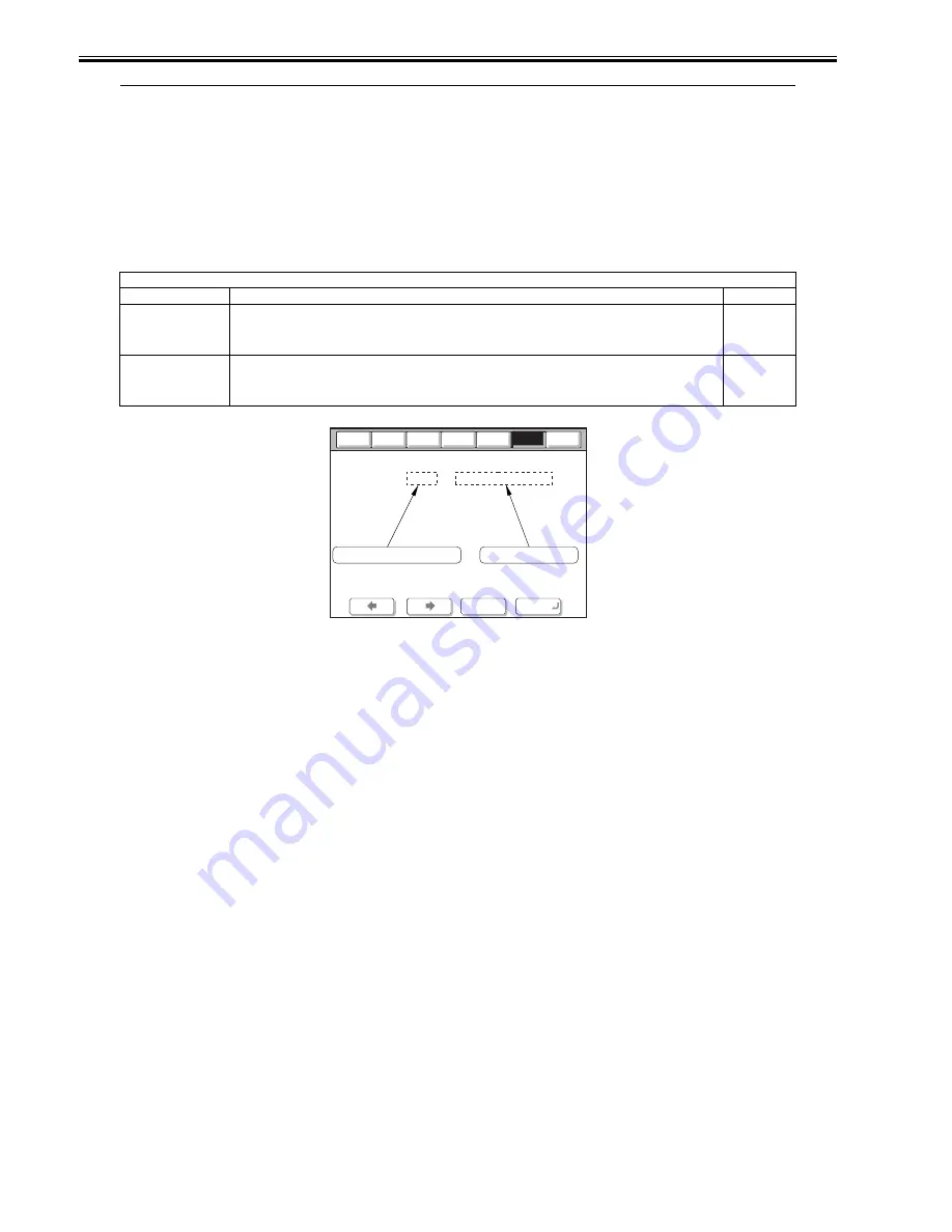
PING
Checks connection between copier and network (during TCP/IP connection only).
Use this item when checking the connection to the network at time of installation or when there is a network connection
problem.
1
BML-DISP
Switching display of the screen in response to support for BMlinks
Settings
0: Normal system status screen [Factory default/After RAM clear]
1: Screen of device display only
2
Operation method 1) Turn the main power switch OFF.
2) Connect the network cable to the copier and turn the main power switch ON.
3) Tell the user's system administrator that copier installation is complete, and have them him/her the network settings.
4) Ask the system administrator to allow you to perform a network connection check, and check the address of the remote host (IP address of the
PC terminal in the user network) to send the PING.
5) Select the COPIER > TEST > NETWORK > PING service mode item, enter the IP address checked in Step 4 on the operation panel's numeric
keypad, and press the OK key.
- If the copier is connected to the network normally, "OK" is displayed (and the procedure is finished).
- If "NG" is displayed, first check the connection of the network cable. If the connection is normal, go to Step 6. If there is a problem with the
network cable's connection, redo the connection and redo Step 5.
6) Select the COPIER > TEST > NETWORK > PING service mode item, enter the loop back address* (127.0.0.1), and press the OK key followed
by the start key.
- If "NG" is displayed, there is a problem with the local TCP/IP settings. Go back to Step 3 and check the settings again.
- If "OK" is displayed, there is no problem with the local TCP/IP settings. However, there could be a problem with the network interface board
(NIC) connection or the NIC itself. Go to Step 7 to check the NIC.
*The loop back address returns the signal in front of the NIC, enabling checking of the local TCP/IP settings.
7) Select the COPIER > TEST > NETWORK > PING service mode item, enter the local host address (local IP address), then press the OK key.
- If "OG" is displayed, there could be a problem with the NIC connection or the NIC itself. In this case, check the NIC connection or replace the
NIC.
- If "OK" is displayed, there is no problem with the local network settings or NIC.
In this case, the problem may be with the user's network environment. Explain the situation to the system administrator, and ask them to deal with
it.
Entered number
Description
Counter
Option
Function
I/O
< NETWORK >
< 1/1 >
< READY >
+/-
OK
Display
Adjust
PING
IP address input
Result display (OK/NG)
0 .
0 .
0 .
0
Test
Summary of Contents for iR C2880 series
Page 1: ...Aug 29 2006 Service Manual iR C3380 2880 Series ...
Page 2: ......
Page 6: ......
Page 23: ...Chapter 1 Introduction ...
Page 24: ......
Page 26: ......
Page 52: ......
Page 53: ...Chapter 2 Installation ...
Page 54: ......
Page 127: ...Chapter 3 Basic Operation ...
Page 128: ......
Page 130: ......
Page 136: ......
Page 137: ...Chapter 4 Main Controller ...
Page 138: ......
Page 160: ......
Page 161: ...Chapter 5 Original Exposure System ...
Page 162: ......
Page 188: ...Chapter 5 5 24 F 5 68 4 Remove the original sensor 2 hook 1 F 5 69 ...
Page 189: ...Chapter 6 Laser Exposure ...
Page 190: ......
Page 192: ......
Page 206: ......
Page 207: ...Chapter 7 Image Formation ...
Page 208: ......
Page 256: ......
Page 257: ...Chapter 8 Pickup Feeding System ...
Page 258: ......
Page 262: ......
Page 303: ...Chapter 9 Fixing System ...
Page 304: ......
Page 306: ......
Page 321: ...Chapter 10 Externals and Controls ...
Page 322: ......
Page 326: ......
Page 336: ...Chapter 10 10 10 F 10 10 2 Remove the check mark from SNMP Status Enabled ...
Page 337: ...Chapter 10 10 11 F 10 11 ...
Page 359: ...Chapter 11 MEAP ...
Page 360: ......
Page 362: ......
Page 401: ...Chapter 12 RDS ...
Page 402: ......
Page 404: ......
Page 411: ...Chapter 13 Maintenance and Inspection ...
Page 412: ......
Page 414: ......
Page 416: ...Chapter 13 13 2 F 13 1 8 9 1 2 3 3 5 6 7 10 11 12 13 14 4 ...
Page 421: ...Chapter 14 Standards and Adjustments ...
Page 422: ......
Page 424: ......
Page 431: ...Chapter 15 Correcting Faulty Images ...
Page 432: ......
Page 434: ......
Page 459: ...Chapter 16 Self Diagnosis ...
Page 460: ......
Page 462: ......
Page 481: ...Chapter 17 Service Mode ...
Page 482: ......
Page 484: ......
Page 571: ...Chapter 18 Upgrading ...
Page 572: ......
Page 574: ......
Page 603: ...Chapter 19 Service Tools ...
Page 604: ......
Page 606: ......
Page 609: ...Aug 29 2006 ...
Page 610: ......


