2
3
1
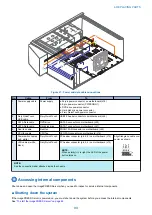
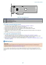
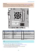
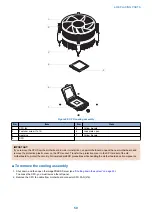
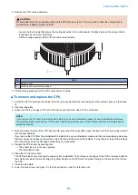
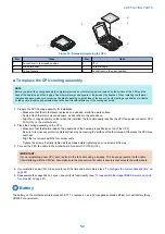
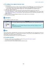
Figure 26: Printer interface board
No.
Item
1
Switch (positioned to 1-3m)
2
Printer interface cable connector
3
PCIE x16 connector
● To remove the printer interface board
1. Shut down and open the imagePRESS Server (see
“Shutting down the system” on page 33
To remove the printer interface board, you must remove the left panel.
2. Remove the printer interface cable that connect the printer interface board and the printer.
3. Remove the board mounting bracket screw that attaches the printer interface board to the chassis.
4. Remove the printer interface board from the chassis.
Grasp the printer interface board at the front and back edges and gently pull the board straight out of its motherboard
connector.
5. Place the printer interface board in an antistatic bag.
● To replace the printer interface board
1. Insert the board into the PCIE x16 slot on the motherboard. (see
“Removing the motherboard” on page 42
)
The printer interface board edge connector is keyed to fit in the motherboard connector only when properly oriented.
2. Secure the board to the chassis with the board mounting bracket screw that you removed earlier.
3. Reassemble the
imagePRESS Server
and verify its functionality. (see
“To reassemble the imagePRESS Server and verify
)
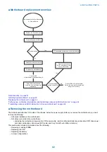
Motherboard
IMPORTANT:
If you are removing the motherboard in order to replace it with a new motherboard, review the roubleshooting and
motherboard cautions on
“Replacing the motherboard” on page 44
.
The CPU mounted on the motherboard controls the image data transferred to and from the printer interface board. The
motherboard also controls hard disk drive functions and the communication between the imagePRESS Server and external
devices.
4. REPLACING PARTS
41
Summary of Contents for ImagePRESS Server H350 V2
Page 8: ...Introduction 1 Introduction 2 Specifications 7 ...
Page 17: ...INSTALLING HARDWARE 2 Installing Hardware 11 ...
Page 26: ...USING THE IMAGEPRESS SERVER 3 Using the imagePRESS Server 20 ...
Page 35: ...REPLACING PARTS 4 Replacing parts 29 ...
Page 86: ...INSTALLING SYSTEM SOFTWARE 6 Installing System Software 80 ...
Page 91: ...TROUBLESHOOTI NG 7 Troubleshooting 85 ...
Page 104: ...INSTALLATION PROCEDURE 8 Installation 98 Removable HDD Kit B5 108 ...


