background image

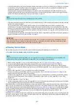
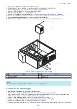
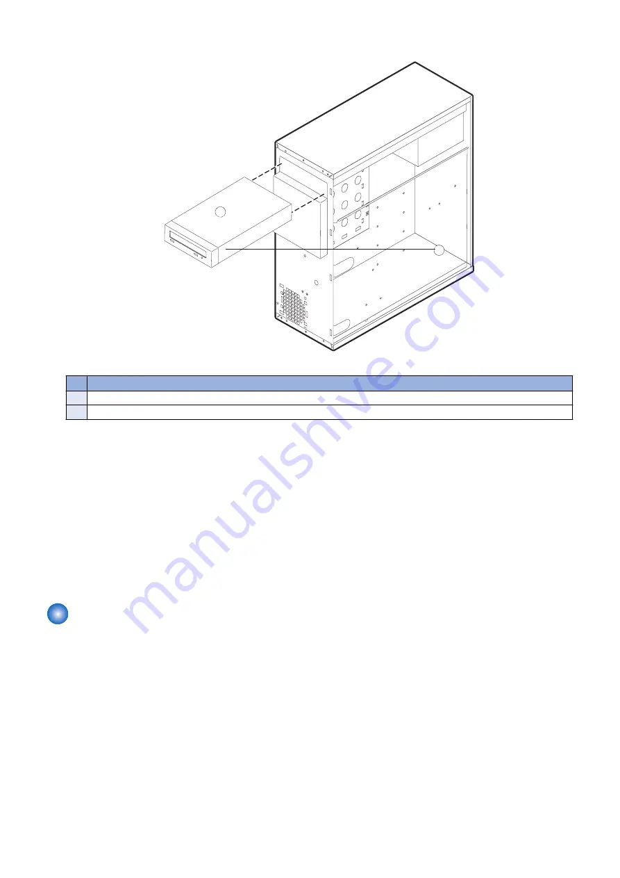
3. Release the front latches on both side of the DVD drive by squeezing the levers, and pull the DVD drive out of the slot.

1

2

Figure 36: Removing/replacing the DVD drive

No.

Item

1

Latch lever (1/2)

2

DVD drive

4. If you are replacing the DVD drive with new one, remove the eight screws on the side of the DVD drive and remove the ears.

Set aside the screws so that you can replace them later.

■ To replace the DVD drive

1. If you are installing the new DVD drive, attach the ears on both side of the DVD drive using the eight screws you removed

earlier.

2. Insert the DVD drive into the front panel cutout until the latch snaps.
3. Connect the data/power cables to the connectors on the back of the DVD drive.

Make sure that the other ends of the power and data cables are connected to the power supply and SATA0 (J50) on the
motherboard.

4. Reassemble the 

imagePRESS Server

 and verify its functionality (see 

“To reassemble the imagePRESS Server and verify

functionality” on page 61

)

 Restoring and verifying functionality after service

Before you leave the customer site, make sure that you complete the following steps. If you cannot complete a step, determine
the reason and correct the problem before continuing. For more information, see 

“Troubleshooting” on page 85

.

■ To reassemble the imagePRESS Server and verify functionality

1. Reseat all boards, cables, connectors, and other parts loosened or removed during service.

When routing cables inside the 

imagePRESS Server

, make sure that:

• Covers are securely installed after routing cables
• Cable routing does not interfere with the operation of internal components nor interfere with removing or replacing

components

• Cables are not tangled nor looped around internal circuit boards or components (such as capacitors and resistors)
• Cables do not lie on or against any internal heating element
• Cables do not interfere with opening or closing 

imagePRESS Server

 panels

• Cable slack is secured with a tie-wrap

2. Restore the 

imagePRESS Server

 to the upright position.

4. REPLACING PARTS

61

Summary of Contents for ImagePRESS Server H350 V2

Page 1: ...SERVICE MANUAL imagePRESS Server H350 V2 Canon July 16 2020 Rev 1 1 COPYRIGHT 2020 CANON INC CANON imagePRESS Server H350 V2 Rev 1 1 PRINTED IN U S A ...

Page 2: ...ademarks and service marks of Mopria Alliance Inc in the United States and other countries Unauthorized use is strictly prohibited Apple AppleTalk Bonjour iPad iPhone iPod touch Mac OS X and Safari are trademarks of Apple Inc Microsoft Windows Windows Vista Windows Server Internet Explorer Microsoft Edge Excel and PowerPoint are either registered trademarks or trademarks of Microsoft Corporation i...

Page 3: ...s The following symbols are used throughout this Service Manual Symbols Explanation Symbols Explanation Check 1x Remove the claw Check visually 1x Insert the claw Check a sound Push the part 1x Disconnect the connector Connect the power cable 1x Connect the connector Disconnect the power cable 1x Remove the cable wire from the cable guide or wire saddle Turn on the power 1x Install the cable wire ...

Page 4: ...gnal is High while 0 is used to indicate Low The voltage value however differs from circuit to circuit In addition the asterisk as in DRMD indicates that the DRMD signal goes on when 0 In practically all cases the internal mechanisms of a microprocessor cannot be checked in the field Therefore the operations of the microprocessors used in the machines are not discussed they are explained in terms ...

Page 5: ...out the installation process 11 Checking the customer site 11 Setting customer expectations 12 Unpacking the imagePRESS Server 13 Connecting the imagePRESS Server 13 3 USING THE IMAGEPRESS SERVER 19 Using the imagePRESS Server 20 Fiery Ticker 20 Command WorkStation 21 About Configure 21 Fiery QuickTouch 21 Quick Launch 24 Quick options 24 Network status LEDs 25 Starting shutting down restarting an...

Page 6: ...ble USB flash drive 70 Backing up the system configuration 71 To save the system configuration using WebTools 71 Restoring the system configuration 72 To restore the system configuration using WebTools 72 Using Fiery System Installer 73 Backup with Fiery System Installer 73 Restore with Fiery System Installer 74 To restore the system using Fiery system installer 74 Using bootable USB storage devic...

Page 7: ...onditions 89 Troubleshooting information 93 Cleaning the imagePRESS Server 95 8 INSTALLATION PROCEDURE 97 Installation 98 Before Connection 98 Installation Procedure 99 Settings After Installation 105 Removable HDD Kit B5 108 Before and after installing the HDD Security Option 108 Contents iii ...

Page 8: ...Introduction 1 Introduction 2 Specifications 7 ...

Page 9: ...ce document describes how to install imagePRESS Server system software and how to service the imagePRESS Server hardware It is not intended for customer use Information about the printer network remote computers software applications and imagePRESS Server operating system is not included in this document Illustrations In this document illustrations reflect the version of the imagePRESS Server bein...

Page 10: ...e image frame buffer memory to the printer interface board The raster data is sent to the printer which then renders the image on paper at maximum speed Before you service the imagePRESS Server Before you service the imagePRESS Server it is strongly recommended that you make sure that you have the required tools see Tools you will need on page 3 and carefully review all precautions see Precautions...

Page 11: ...oom temperature Avoid magnets Keep magnets and magnetic sensitive objects away from electronic components especially the hard disk drive Avoid fan blades WARNING The imagePRESS Server contains hazardous moving parts When servicing the imagePRESS Server keep away from moving fan blades Attention ce produit contient des pièces mobiles dangereuses Veuillez le maintenir à l écart des pales de ventilat...

Page 12: ...er outlet Do not pull the cable to unplug the imagePRESS Server Instead pull the plug Do not tamper with or disable the power cable grounding plug Do not use an extension cord Do not have liquids near the imagePRESS Server If liquid spills on the imagePRESS Server immediately unplug the imagePRESS Server Do not open the power supply For more information about the power supply see Power supply on S...

Page 13: ... non può sostenere il peso dell intero sistema WARNUNG Heben Sie den Druckserver nicht an der oberen Gehäuseabdeckung an Die obere Gehäuseabdeckung ist nicht dafür ausgelegt das Gesamtgewicht des Systems zu tragen ADVERTENCIA No levante nunca el servidor de impresión agarrándolo por el panel superior El panel superior no soporta el peso del sistema ADVERTÊNCIA Nunca erga o servidor de impressão pe...

Page 14: ... 1X DHCP DNS NTP Direct Print format PDF1 7 EPS TIFF6 JDF1 4 JMF OP VDP FreeForm v1 v2 1 PPML PDF VT 1 PDF VT 2 Creo VPS Fiery Print Controller Standard Fea tures Fiery Command WorkStation6 Paper Catalog Fiery Spot On Fiery Remote Scan Fiery Hot Folders Virtual Printers Fiery JDF Fiery Print Controller Options Fiery Impose Fiery Compose Fiery Impose and Compose Fiery Graphic Arts Package Premium E...

Page 15: ...27 Win Mac Impose Compose 6 0 0 15 Win Mac Command WorkStation 6 5 0 32 Win Mac Fiery Remote Scan 6 7 0 25 Win Mac Hot Folder 4 01 0 09 Win EFI Printer Delete Utility 3 4 0 10b Mac Fiery Software Uninstaller 1 9 0 11 Checking the Service Mode of Connection Engine When connecting this machine it is necessary to select the engine service mode COPIER OPTION INT FACE and set IMG CONT to 3 When the con...

Page 16: ...r you log on to the Fiery server change the Fiery password for Fiery Windows OS and the Fiery system to prevent unauthorized usage NOTE Use Configure in WebTools or Fiery Setup Wizard to change the Fiery password Notes on the default password The Fiery documentation may mention Fiery 1 as the default password Do not use this password when you log on to the Fiery server for the first time Instead u...

Page 17: ...INSTALLING HARDWARE 2 Installing Hardware 11 ...

Page 18: ...ent work with the site administrator to configure a static IP address see Configuring a static IP address for the imagePRESS Server on page 17 6 Complete the installation see Completing installation on page 18 Remind site administrator to install current user software on client computers that print to the imagePRESS Server see Printing and Utilities which are part of the user documentation set Cha...

Page 19: ...trical outlet that will supply power to the imagePRESS Server Do not run the imagePRESS Server and the printer on the same circuit If the customer has provided one use a surge suppressor for the imagePRESS Server Network Make sure that the network is available at the time set for installation Verify with the network administrator that the network is functioning before you attach the imagePRESS Ser...

Page 20: ... not immediately discard packing materials 1 Open the box and remove the packing material Save the original boxes and packing material in case you need to transport the imagePRESS Server at a later date 2 Remove the contents from the top accessory tray Inspect the contents for visible damage 3 Set aside the remaining components from the top container 4 Remove the top container and any packing mate...

Page 21: ...n the Fiery QuickTouch for keyboard mouse connec tions for the service purpose 7 Power switch Power On O Power Off 8 Type A USB 2 0 ports x2 3 Fiery QuickTouch reset button 9 Network port Upper RJ 45 4 Power button 10 Display port for optional monitor 5 Front panel door 11 DVI port for optional monitor 12 Type A USB 3 0 ports x2 13 Crossover Ethernet port Lower RJ 45 14 Printer interface port 2 IN...

Page 22: ...any the furniture 2 Connect the monitor cable to the DVI port or Display port on the connector panel 3 Connect the monitor power cable to an outlet of the power strip inside the furniture or an outlet on the wall 4 Place the keyboard and mouse on the furniture table top 5 Connect the wireless adapter for the keyboard and mouse to one of the USB ports Use the USB ports that is attached at the front...

Page 23: ...arrangements are different NOTE Align Cables side by side and examine wires To connect imagePRESS Serverto the network 1 Make sure that the is powered off 2 Make sure that the network cable is connected to the customer site network 3 Connect the network cable to the upper RJ 45 network port on the back of the imagePRESS Server see Connecting the imagePRESS Server on page 13 IMPORTANT The straight ...

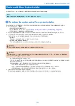
Page 24: ...ease the button to power on the system The power supply automatically senses the correct voltage Figure 7 imagePRESS Server power button 3 Check the activities on the Fiery QuickTouch The power supply automatically senses the correct voltage Allow the startup to proceed without interruption Do not press any buttons while the system is starting Configuring a static IP address for the imagePRESS Ser...

Page 25: ...ouch panel verify that the printer interface cable is connected properly to the printer and the imagePRESS Server 4 Perform any required system software upgrades For instructions see the documentation that accompanies the imagePRESS Server system upgrade Updates to imagePRESS Server software may be available from a variety of sources for example System Updates see Installing software patches on pa...

Page 26: ...USING THE IMAGEPRESS SERVER 3 Using the imagePRESS Server 20 ...

Page 27: ...n describes how to print the Test Page Server Configuration page and other Fiery pages Test Page verifies that all components of the imagePRESS Server to printer interface work The Test Page is a pre stored page stored on the imagePRESS Server hard disk drive NOTE Information regarding Test Page refers to PS Test Page or PCL Test Page For more information see Configuration and Setup which is part ...

Page 28: ...m Command WorkStation or WebTools For information about using Configure see the Command WorkStation Help To access Configure from an Internet browser 1 Open an Internet browser and type the IP address of the imagePRESS Server NOTE If a message about an untrusted connection appears or you are asked whether you want to proceed you can safely ignore the message and proceed by clicking Continue to web...

Page 29: ...displays various screen elements No Item No Item 1 imagePRESS Server name and status Pressing the Fiery icon shows more information about the imagePRESS Server and the network address 6 Number of pages and copies that are printing 2 Icon of the print job type If there are no print jobs being processed an Idle status dis plays 7 Queued jobs list Pressing the Queue icon shows a list of jobs that are...

Page 30: ...ob list shows queued jobs and detailed information about each job Figure 11 Queue job window The Printed jobs list provides job status and details about the jobs that have been printed Q HLWKHU WKH 4XHXH MREV RU 3ULQWHG MREV VFUHHQ RX FDQ WDS Back WR JR EDFN WR WKH RPH VFUHHQ Figure 12 Printed jobs window In either the Queue jobs or Printed jobs screen you can press Back to go back to the Home scr...

Page 31: ...sing Fiery System Restore or Settings you must log in as an administrator For more information on backing up and restoring the imagePRESS Server see Performing Backup and Restore on page 64 Quick options The Quick Options menu can be accessed by pressing the three dot icon on the top right corner of the Home screen Quick Options provide the following general system settings Shutdown system shuts d...

Page 32: ...5 Ethernet network port upper RJ 45 No Item 1 Link Activity indicator 2 Speed indicator Table 1 Network link indicators Link Activity LED Network link status Off No link to network Solid green Valid link to network Flashing green Data transfer is in progress Table 2 Network speed indicators Link Activity LED Network link speed Off 10 Megabits second Green 100 Megabits second Amber 1000 Megabits se...

Page 33: ...eed without interruption Do not press any buttons while the system is starting To shut down restart or reboot from the monitor NOTE The Fiery NX Station including monitor is optional 1 Make sure that the imagePRESS Server is not receiving processing or printing any files If the system just finished processing wait at least five seconds after the system reaches Idle before you proceed 2 Close all a...

Page 34: ...down procedure 2 On the Fiery QuickTouch Home screen press the Quick Options menu button see Overview of Fiery QuickTouch menu options on page 22 3 Do one of the following To shut down the imagePRESS Server select Shutdown system To reboot the entire system including the operating system select Reboot system To restart only the imagePRESS Server system software select Restart server 4 At the confi...

Page 35: ...REPLACING PARTS 4 Replacing parts 29 ...

Page 36: ... throughout this document to refer the re installation of existing components Install new components only when necessary If you determine that a component you removed is not faulty reinstall it NOTE Replacement parts and specifications are subject to change Install the correct parts as directed by your service support center CAUTION When servicing the imagePRESS Server follow Precautions on page 3...

Page 37: ...USB ports on the Fiery QuickTouch for keyboard mouse connec tions for the service purpose 7 Power switch Power On O Power Off 8 Type A USB 2 0 ports x2 3 Fiery QuickTouch reset button 9 Network port Upper RJ 45 4 Power button 10 Display port for optional monitor 5 Front panel door 11 DVI port for optional monitor 12 Type A USB 3 0 ports x2 13 Crossover Ethernet port Lower RJ 45 14 Printer interfac...

Page 38: ...1 2 Figure 19 Inside the front panel No Item 1 DVD drive 2 DVD eject button 4 REPLACING PARTS 31 ...

Page 39: ...rd disk drive data cables 8 CPU 14 DVD drive 3 DVD drive data cable 9 Battery 15 Chassis 4 Printer interface board 10 Motherboard 16 Rear fan 5 Fiery QuickTouch power cable 11 Front panel 17 Fiery QuickTouch display 6 CPU cooling assembly 12 Power supply 18 Top panel NOTE CPU fan cable tie wraps cable clamps dongle s and external cables are not shown 4 REPLACING PARTS 32 ...

Page 40: ...rd J20 6 CPU fan cable CPU fan CPU FAN connector on motherboard J16 7 Power switch cables red white Fiery QuickTouch FP header connector pin 6 8 on motherboard J15 Align triangle on cable con nector as shown Black White White Red 1 2 9 10 8 LED cables white black Fiery QuickTouch FP header connector pin 2 4 on motherboard J15 NOTE When polarity is right the LED of the power button turns on NOTE Se...

Page 41: ...on page 33 2 Wait 10 seconds after the imagePRESS Server powers off and then remove all cables from the back of the imagePRESS Server 3 Remove the imagePRESS Server from the furniture if applicable 4 Remove all external panels necessary to access the component that you need to service At the minimum you must remove the left panel to service the component You may also need to remove other panels de...

Page 42: ... the two screws at the rear left of the chassis Figure 23 Removing the right panel 4 From the back of the unit slide the left side chassis cover toward the rear of the unit and remove To remove the front panel 1 Remove the anchor screw from the front bezel Figure 24 Front bezel anchor screw 4 REPLACING PARTS 35 ...

Page 43: ...nt bezel See To remove the front panel on page 35 3 Slide the right chassis cover into place and secure with two screws on backside of the unit 4 Slide the left chassis cover into place and secure with two screws on backside of the unit Fiery QuickTouch display module Fiery QuickTouch is attached to the top panel of the imagePRESS Server Follow the directions to remove the chassis covers See Openi...

Page 44: ...ws you remove or replace might fall inside the Fiery QuickTouch device To remove the Fiery QuickTouch 1 Follow the instructions to remove the side and front chassis covers 2 To remove the top bezel slide the bezel forward and release it from the top of the chassis 3 Stabilize the unit and set the Fiery QuickTouch on its side atop the unit 4 REPLACING PARTS 37 ...

Page 45: ...cable and a tab on the support bracket for USB connector 2 Remove the power harness by unplugging it 3 Remove the two screws from the USB connector and then unplug the connector CAUTION Use a screwdriver with a magnetic tip so you do not drop a loose screw into the Fiery QuickTouch unit 4 REPLACING PARTS 38 ...

Page 46: ...o Item 1 Power harness connector 2 USB connector 5 Turn the unit so it is faced down on the work surface 6 Remove the single screw in the center then remove the washer and spring washer 4 REPLACING PARTS 39 ...

Page 47: ...re the power cable to the tab on the supporting bracket for USB connector 8 Replace the top bezel on top of the unit and slide back in place 9 Check that the bezel cover extends over the rear sheet metal to be properly in place 10 Replace the chassis panels See To replace the chassis panels on page 36 Removing and replacing boards This section includes procedures for removing and replacing the fol...

Page 48: ... bag To replace the printer interface board 1 Insert the board into the PCIE x16 slot on the motherboard see Removing the motherboard on page 42 The printer interface board edge connector is keyed to fit in the motherboard connector only when properly oriented 2 Secure the board to the chassis with the board mounting bracket screw that you removed earlier 3 Reassemble the imagePRESS Server and ver...

Page 49: ...0 Replacing the motherboard on page 44 Verifying new motherboard installation and transferring options and BIOS information on page 46 Transferring options and BIOS information to the new motherboard on page 48 Removing the motherboard The motherboard attaches to the side of the chassis below the power supply Before you remove the motherboard you must remove the following All boards installed on t...

Page 50: ...wer connector J18 2 Monitor port DisplayPort 8 Battery CR1 14 USB 3 0 header connector J26 3 Monitor port DVI 9 DIMM_A0 15 FP header connector J15 4 Type A USB 3 0 ports x2 10 DIMM_B0 16 SATA 0 DVD drive data cable connector J50 5 8 pin power connector PWRCONN1 11 CPU fan power CPU FAN J16 17 SATA 1 Hard disk drive data cable connector J41 6 CPU cooling assembly 12 Rear fan FRONT FAN J20 18 Clear ...

Page 51: ... solder contacts on the underside of the motherboard especially beneath the battery socket Improper handling can short circuit and permanently damage the motherboard 3 If you are replacing the motherboard with a new motherboard remove the following from the old motherboard DIMM See DIMMs on page 48 CPU See CPU on page 49 Replacing the motherboard IMPORTANT Follow the procedures in this section to ...

Page 52: ...ransfer options Return the new motherboard and motherboard replacement dongle to inventory If you can verify in Service Mode that the new motherboard solves the problem that you are troubleshooting transfer options to the new motherboard using the motherboard replacement dongle included with the new motherboard see Entering Service Mode on page 47 Do not remove the motherboard replacement dongle w...

Page 53: ...fan cable 24 pin motherboard power cable 8 pin x 2 motherboard power cable Fiery QuickTouch power LED cable Fiery QuickTouch USB port cable Hard disk drive cable SATA data cable Power supply cable DVD drive cables Power and data combination cable SATA data cable Rear fan cable 3 Secure cables as necessary with any plastic cable clamp that you may have removed earlier 4 Replace the printer interfac...

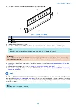
Page 54: ...ia is in the DVD drive you have installed a new motherboard and that you have reassembled the imagePRESS Server and attached external cables 1 Make sure the imagePRESS Server is connected to the printer see To connect to the printer on page 16 2 Locate the motherboard replacement dongle provided with the new motherboard and connect it to a USB port 3 Remove all USB devices except for the keyboard ...

Page 55: ...m the hard disk drive to the BIOS chip on the replacement motherboard NOTE If you select No the process ends and you return to the Functions menu 7 Reboot the imagePRESS Server 8 Remove the motherboard replacement dongle after the imagePRESS Server reaches Idle Replacing parts on the motherboard Before you remove and replace the DIMMs CPU and battery on the motherboard shut down and open the image...

Page 56: ...w DIMM make sure to reset the time and date in Setup see To configure the system date and time on page 54 7 Replace the printer interface board see To replace the printer interface board on page 41 8 Reassemble the imagePRESS Server and verify its functionality see To reassemble the imagePRESS Server and verify functionality on page 61 CPU The CPU is installed in a socket on the motherboard Before...

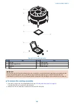
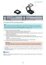
Page 57: ... and remove the protective plastic cover on the CPU socket Transfer the protective cover to the CPU socket of the old motherboard to protect the circuitry Follow standard ESD precautions while handling the motherboard and all components To remove the cooling assembly 1 Shut down and then open the imagePRESS Server see Shutting down the system on page 33 To access the CPU you must remove the left p...

Page 58: ...move the protective plastic cover from the CPU socket Transfer the protective cover to the CPU socket of the old motherboard to protect the circuitry 4 Wipe the contact surface of the CPU the smooth gray side of the chip with a clean lint free cloth to ensure proper contact with the new heatsink If you remove the CPU from the motherboard to install it on a new motherboard make sure that you comple...

Page 59: ...ower connector CPU FAN J16 on the motherboard 2 Place the cooling assembly on the CPU Make sure that the thermal pad on the underside of the heatsink is positioned on top of the CPU Be sure to remove any protective material that may be covering the surface of the thermal pad Otherwise the CPU may overheat Align the four screws with the four screw posts Tighten the screws Partially tighten all the ...

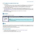
Page 60: ...r una batería del mismo tipo que recomienda el fabricante Deseche las baterías usadas respetando la normativa local ATTENZIONE Esiste pericolo di esplosione se la batteria viene sostituita con una di tipo non corretto Sostituirla solamente con un tipo raccomandato dal produttore Lo smaltimento delle batterie usate deve essere eseguito secondo le normative locali AVISO Existe o perigo de explosão s...

Page 61: ...ngs and specify the current date and time and click Save 5 Click Log Out to exit Configure Jumpers Jumper configurations should not be changed Jumper Description J101 Pin 1 J101 is the Clear CMOS and Password jumper Default configuration jumper cap installed on pins 1and 2 NOTE It is not necessary to clear the CMOS settings when servicing motherboard components the DVD drive and the hard disk driv...

Page 62: ...see To reassemble the imagePRESS Server and verify functionality on page 61 Power supply This section describes how to remove and replace the power supply For more information about the power supply see Physical specifications on page 7 CAUTION Do not open the power supply for service or troubleshooting purposes Opening the power supply will void the warranty To remove the power supply 1 Shut down...

Page 63: ... replacing the power supply No Item No Item 1 Power supply unit 3 Screw 1 of 4 2 Chassis bar 4 Inside screw NOTE To service the power supply place the imagePRESS Server in an upright position To replace the power supply 1 Make sure that the imagePRESS Server is in upright position 2 Position the power supply inside the chassis see To remove the power supply on page 55 Insert the power supply unit ...

Page 64: ... if the problem persists If it does perform other procedures such as replacing the motherboard see Replacing the motherboard on page 44 Proper handling IMPORTANT Improper handling can damage a hard disk drive Handle the hard disk drive with extreme care Use proper ESD practices when grounding yourself and the imagePRESS Server Keep magnets and magnetic sensitive objects away from the hard disk dri...

Page 65: ...e bracket off the bracket shelf IMPORTANT Avoid striking the DIMMs as you remove the hard disk drive bracket NOTE You will encounter slight resistance as you slide the bracket off the shelf The resistance is caused by two tension points on the bottom of the bracket The resistance helps control the bracket s movement during removal and installation 1 2 3 4 5 Figure 34 Removing replacing the hard di...

Page 66: ...e appropriate system software see Installing System Software on page 80 To replace the hard disk drive IMPORTANT Do not install a new hard disk drive and a new motherboard at the same time If you suspect that the imagePRESS Server needs a new hard disk drive and a new motherboard first install the new hard disk drive and install system software then install a new motherboard and transfer options s...

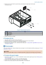
Page 67: ...fy functionality on page 61 9 If you replaced the hard disk drive with a new hard disk drive install system software see Installing System Software on page 80 If a startup error displays on the Fiery QuickTouch when you power on the imagePRESS Server check the connections 10 Verify functionality see To reassemble the imagePRESS Server and verify functionality on page 61 DVD drive The DVD drive is ...

Page 68: ...emble the imagePRESS Server and verify functionality on page 61 Restoring and verifying functionality after service Before you leave the customer site make sure that you complete the following steps If you cannot complete a step determine the reason and correct the problem before continuing For more information see Troubleshooting on page 85 To reassemble the imagePRESS Server and verify functiona...

Page 69: ...twork on page 16 10 Ask the site administrator to download a test job over the network If the job does not print or has poor image quality see printing problems and the Troubleshooting sections of the user documentation Servicing the imagePRESS Server with furniture This chapter describes how to remove the imagePRESS Server from the furniture in order to access internal components for service For ...

Page 70: ...nd Restore 68 Backing up or restoring the imagePRESS Server 69 Backing up the system configuration 71 Restoring the system configuration 72 Using Fiery System Installer 73 Restore with Fiery System Installer 74 Using bootable USB storage device to restore 75 Platform Utilities 76 Fiery Deployable Image 77 ...

Page 71: ...ools Fiery Resources and Settings Restore Complete Fiery Server WebTools Backup and Restore Fiery System Image Backup Now USB New image Fiery Factory image Internal hard drive Schedule Backup Internal HDD Internal HDD Automatic Manual bootable backup on USB non bootable backup on HDD WebTools Backup and Restore Fiery System Image if Fiery is Functional Restore Restore from a local image Restore fr...

Page 72: ...and Restore see Using Backup and Restore on page 68 Fiery System Installer see Using Fiery System Instal ler on page 73 4 Backup and Restore in WebTools or Fiery Quick Touch Backup and Restore Fiery System Image Back up Now USB Fiery factory image Factory default image factory prein stalled recovery backup Includes factory default version of software and configuration settings Does not include pri...

Page 73: ...as hed this im age is not ac ces si ble Network lo cation If bootable can restore directly from USB see Using boota ble USB stor age device to restore on page 75 Backup and Restore see Using Backup and Restore on page 68 Fiery System Installer see Using Fiery System Instal ler on page 73 7 Fiery System Installer on Sys tem Software DVD1 Fiery System Installer Backup hard disk drive s Customized im...

Page 74: ... exist create a new one after installing all available software updates The backup image may be saved to or found in any of the following locations Local Disk USB drive External hard disk Network If you do not have a backup with the system settings and jobs the system can access a preinstalled recovery backup on the hard disk drive provided with the imagePRESS Server See To restore the backup imag...

Page 75: ...rver menu select Device Center 3 In Device Center select Tools Fiery Resources and Settings or Fiery System Image The Backup and Restore will display on the default web browser window To access Backup and Restore from WebTools 1 Open an Internet browser and type the IP address of the imagePRESS Server NOTE As a security measure WebTools is designed to work only over Hyper Text Transfer Protocol Se...

Page 76: ...table image option to make the USB flash drive a bootable device Fiery factory image Select this option if you want to create a backup of the imagePRESS Server factory image When you select this option the Create bootable image option enables automatically If you select Create bootable image option the USB device or hard disk drive specified as a destination becomes a bootable device Select this o...

Page 77: ...accessible from the imagePRESS Server If you want restore the backup image stored on the USB flash drive attach the USB flash drive to one of the USB 3 0 ports on the imagePRESS Server 4 Select one of the following restore options Restore from a local image Restore from a USB storage device Restore from the factory default image 5 Click Continue 6 Follow the on screen prompts to restore the backup...

Page 78: ...strator to archive custom color profiles preflight presets FreeForm masters customer installed fonts and the Job Log to removable media or a network location To save the system configuration using WebTools 1 Access WebTools 2 On the left side choose Backup and Restore 3 In the Backup and Restore window click Fiery Resources and Settings 4 In the Fiery Resources and Settings window click Backup Now...

Page 79: ...dministrator to restore any archived settings and files For more information see Configuration and Setup which is part of the user documentation set To restore the system configuration using WebTools 1 Access WebTools 2 On the left side choose Backup and Restore 3 In the Backup and Restore window click Fiery Resources and Settings 4 In the Fiery Resources and Settings window click Restore 5 In the...

Page 80: ...lable in the system or in any attached devices you can only perform the restore from the recovery partition Back up hard disk drive s Use this option when you create the system backups You can specify the location of the backup file name and other attributes of the backups Platform Utilities You can perform the backup management tasks from this option such as erasing hard disks or using Windows Ta...

Page 81: ...or you to choose Restore from recovery partition This restores the server from a hard disk drive partition to its factory built settings CAUTION Any custom settings you have specified after installation are over written CAUTION If you perform restore from recovery partition the Fiery default password will be set to Fiery 1 Make sure to change the password after restoring from recovery partition Se...

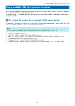
Page 82: ...ith the Create bootable media option If you have created a backup as bootable backup image follow these instructions NOTE You can use this procedure to also install the system software after you replaced the HDD with a new one 1 Shut down theimagePRESS Server 2 Attach the bootable USB backup media to the imagePRESS Server Make sure to remove any media in the DVD drive Do not attach other USB devic...

Page 83: ...ro Quick erase for writing zeros to all disk sectors Advanced backup management Allows the Administrator to Load backup settings from a USB drive to apply to system backup images Save or restore backup history files Search for backup images created on a replaced system to be applied to the current one Launch Windows Task Manager Starts the Windows Task Manager Windows Task Manager displays the pro...

Page 84: ... minimum 2GB and a maximum of 32GB available space respectively NOTE Due to a Windows file system restriction the maximum size of the bootable USB flash drive you can use is 32GB The second USB drive can have more than 32GB of available space The minimum size required for the second USB drive depends on the actual size of the backup file Use a USB HDD formatted with NTFS file system NOTE The image...

Page 85: ...bootable USB storage device with the Fiery deployable image Connect a monitor keyboard and mouse to the imagePRESS Server NOTE You can also use this procedure to install the system software after you replace the HDD with a new one 1 Shut down the imagePRESS Server 2 Attach the bootable USB backup media with the Fiery deployable image which was created using To create a deployable image on page 77 ...

Page 86: ...INSTALLING SYSTEM SOFTWARE 6 Installing System Software 80 ...

Page 87: ...ser software including Command WorkStation using the User Software DVD Server Configuration page Before you reinstall a new version of system software print the Server Configuration page The Server Configuration page provides a record of the customer s current Setup configurations Backing up and restoring the configuration All Setup configurations as well as all custom files and templates stored o...

Page 88: ...tallation may fail 2 If you are installing system software back up the system configuration if possible For more information see Installing system software on page 80 Installing or upgrading the system and user software with Fiery System Installer You can use the imagePRESS Server or Fiery QuickTouch to use Fiery System Installer You can also use a monitor mouse and keyboard attached if available ...

Page 89: ...agePRESS Server see Starting shutting down restarting and rebooting on page 26 3 Install any required software patches by System Updates see Installing software patches on page 83 4 Optional Set up the proxy configuration if you have a proxy server In Configure click Network Proxy Select Enable HTTP Proxy If you choose Manual you input the following items Address Port User name Password Save your ...

Page 90: ...agePRESS Server see the Server Configuration page that you printed before reinstalling You may also need to reinstall software patches as part of upgrading system software After you know which software patches are required for your system you can download them from System Updates or WebTools To download software patches from System Updates 1 From the Windows Start menu click All apps Fiery System ...

Page 91: ...TROUBLESHOOTI NG 7 Troubleshooting 85 ...

Page 92: ...x obvious problems It describes how to eliminate any problems with external connections to the back of the imagePRESS Server and then addresses checking internal board and cable connections Check external and internal connections before replacing any components NOTE Verify that the network is functioning no unauthorized software or hardware is installed on the imagePRESS Server and no problems hav...

Page 93: ...Inspecting the system IMPORTANT If your initial checks of the cable and board connections do not fix the problem you may need to inspect the system on a component by component basis as described in Inspecting the system A comprehensive inspection allows you to verify that each hardware component is properly installed and configured and helps you avoid replacing expensive components unnecessarily I...

Page 94: ...ee Starting shutting down restarting and rebooting on page 26 Shut down the imagePRESS Server wait one minute and then power on the imagePRESS Server by pressing the power button on the right side of Fiery QuickTouch see Starting shutting down restarting and rebooting on page 26 Reset the Fiery QuickTouch press the reset button on the Fiery QuickTouch through the pinhole and hold the button down f...

Page 95: ...r supply Power supply on page 55 The hard disk drive required is Present Correctly installed Not visibly damaged Hard disk drive data cable is Present Firmly connected to the correct SATA connectors on the motherboard see Hard disk drive on page 57 Not visibly damaged Hard disk drive power cables is Present Firmly connected to the SATA power connectors on the hard disk drives Not visibly damaged H...

Page 96: ...ystem software and so forth do not solve the problem and you suspect that the hard disk drive or motherboard is faulty note that it is highly unlikely that the hard disk drive and the motherboard are both defective therefore avoid replacing both to solve one problem Always troubleshoot in the following order 1 Replace the hard disk drive and install system software Always replace a faulty hard dis...

Page 97: ...display module 1 Recheck all cables and connections 2 Use a different power LED cable 3 If the problem persists and you have verified that the power supply and motherboard are function ing properly as described earlier replace the Fiery QuickTouch display module see Fiery Quick Touch display module on page 36 Fiery Ticker messages Please check Fiery Hardware Possibly one of the followings Network ...

Page 98: ... imagePRESS Server motherboard during service and the time and date were not configured in Setup afterward the imagePRESS Server will hang during the user software installa tion segment User Software DVD is corrupted The DVD drive is faulty The hard disk drive is faulty 1 Set the time and date in the BIOS Power off the imagePRESS Server and re move the User Software DVD when it ejects If not alrea...

Page 99: ...er s network is not using DHCP Ethernet interface on the imagePRESS Server motherboard is faulty System software is corrupted 1 If the problem persists ask the network adminis trator to check Network Setup To configure a static IP address if applicable for the customer site as in a non DHCP environment work with the network administrator as described on Con figuring a static IP address for the ima...

Page 100: ...ecessary See the service documentation that accompanies the printer Print quality is poor Possibly one of the following A file or application problem A missing or outdated printer description file The application cannot find the appropriate printer description file The system is out of calibration 1 Print a imagePRESS Server Test Page 2 If the quality of the imagePRESS Server Test Page is good the...

Page 101: ...ways Whether the error has occurred with more than one file Whether the file selected for the report is the same file that had the error Operating system version if the print job was sent from a client computer Version of imagePRESS Server user software installed Description of any other actions performed on the imagePRESS Server during the same time period 2 Optional To include the raster in the ...

Page 102: ... the chassis Noise from the fans Short circuit or damage on the board assembly As a regular maintenance it is important to remove dust on the fans and air duct to keep the airflow inside the chassis WARNING Before you open the imagePRESS Server it is strongly recommended that you review Precautions on page 3 to avoid injury or damage to the imagePRESS Server In addition keep following in mind To p...

Page 103: ...m 1 Power supply fan use the vacuum cleaner from outside of the chassis 3 Rear fan use the vacuum cleaner from outside of the chas sis 2 CPU fan use air dust blower After completing the cleaning reassemble the imagePRESS Server and verify its functionality see To reassemble the imagePRESS Server and verify functionality on page 61 7 TROUBLESHOOTING 96 ...

Page 104: ...INSTALLATION PROCEDURE 8 Installation 98 Removable HDD Kit B5 108 ...

Page 105: ...de Essential Items to Be Performed Before Installation Turn OFF the main power of the host machine and disconnect the power plug from the outlet WARNING If performing work without disconnecting the power plug of the host machine it may cause electrical shock If disconnecting the power plug without turning OFF the main power it may cause damage of the machine When turning OFF the main power follow ...

Page 106: ... Cable 3 0 m for network connection Cross Ethernet Cable 3 0 m 1x M3x6 4x 1x 1x Install with the Power Supply Cord which will be sent separately Others Including guides Installation Procedure Installing the Open I F PCB 1 4x 2 1x 8 INSTALLATION PROCEDURE 99 ...

Page 107: ...ace Cover 2x NOTE The removed screws will be used in step 8 5 1x 1x NOTE The removed screws will be used in step 8 6 NOTE Ask the user to keep the removed Bypass PCB 2x 1x NOTE The removed screws will be used in step 8 8 INSTALLATION PROCEDURE 100 ...

Page 108: ... PCB 2 while paying attention not to trap cables 10 CAUTION Be sure to turn over the 2 Lock Levers and push in the Main Controller PCB 2 When installing the screws install the lower screw first and then the upper one Be sure to perform the work in the order from 1 to 5 in the figure because the connector of the Main Controller PCB 2 may not be connected 2x 8 INSTALLATION PROCEDURE 101 ...

Page 109: ...2 CAUTION When installing the Box Left Cover be careful not to trap cables 4x Installing the imagePRESS Server 1 Place the imagePRESS Server in the installation position 2 NOTE Connect the other end of the Interface Cable that is connected in Installing the Open I F PCB 1x 3 8 INSTALLATION PROCEDURE 102 ...

Page 110: ...rk cable with Category 5e or higher In addition a shielded type STP cable is recommended When using the non shielded type UTP cable it may influence the surrounding electronic equipments via network cable Straight Ethernet Cable 3 0 m for network connection 1x 8 Connect the power plug to the outlet of the host machine 8 INSTALLATION PROCEDURE 103 ...

Page 111: ...ost machine again is displayed on the Touch Panel turn OFF the main power switch It may take approx 10 minutes before the message appears CAUTION The imagePRESS Server is automatically restarted only at the first time when it is connected It takes about approx 5 minutes until it is ready for use Do not press the buttons on the imagePRESS Server until it is ready for use 13 Turn ON the main power s...

Page 112: ...tallation 1 Select Fiery from the main menu on the host machine s LCD 2 Select Login to log in as a system administrator Input of password A password input screen is displayed at the time of installation Entering Fiery password in the password field displays the setting screen NOTE On the Fiery Server Configuration page look for ID in the BIOS Setup section The alphanumeric characters in the ID fi...

Page 113: ...even if there is no change The setting will not be completed unless Save Changes is pressed 5 Press Exit Setup after all settings are completed 6 The confirmation screen will appear and then press Reboot Now 7 The imagePRESS Server will be restarted approx 10 min Checking the Operation After Making the Settings Output Test Page and Configuration by the following procedure and check the connection ...

Page 114: ...logo then press Info Print Pages Configuration 3 Select Info Print Pages PS Test Page 1 2 3 4 Press Yes Connecting to the Network Ask the network administrator to connect to the network make settings and output the test print Refer to Configuration and Setup in User s Manual for details of checking work Executing Image Quality Adjustment Execute the image quality adjustment shown below at installa...

Page 115: ... 6 7 4 5 6 A B a b 1 2 4 7 No Item No Item A Standard Configuration front view a and side view b B HDD Security Option front view a and side view b 1 DVD drive 4 DVD drive 2 Front faceplate 5 Removable HDD 3 HDD in HDD bracket not visible or accessible at front panel 6 2 bay cover 7 Empty HDD bracket not visible or accessible at front panel NOTE Cables motherboard and front door are not shown Opti...

Page 116: ...o install the HDD in a removable enclosure 1 Unpack the Removable HDD Enclosure kit 2 Separate the drive cover and drive carrier from the receiving frame Remove the bag of screws the set of security keys and any other loose items from the drive carrier Using the handle pull the drive carrier out of the receiving frame Hold the unit upside down and remove the drive cover 1 2 3 4 5 6 7 8 9 No Item N...

Page 117: ...rrier into its receiving frame The Fiery server will not boot to Idle unless the HDD drive carrier is locked into its receiving frame 7 Reassemble the Fiery server for details see the Installation and Service Guide Tighten the mounting bracket two screws Reinstall in order the front right and left panels IMPORTANT Do not attempt to install the upper faceplate of the front panel It will not be used...

Reviews: