No.
Parts Name
17
Power supply
18
Power switch
19
Chassis
20
Power supply duct
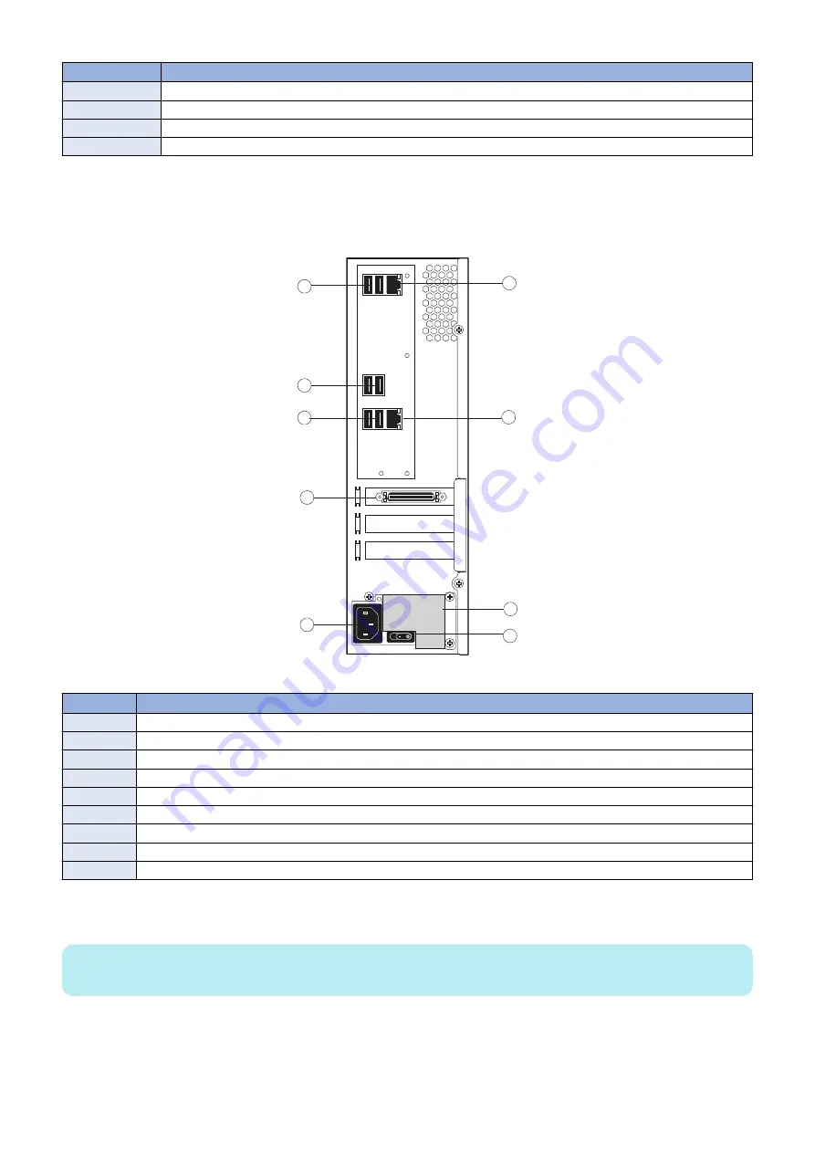
■ imagePRESS Server connector panel and LED diagnostic codest
The connector panel of the
imagePRESS Server
has the external connectors and power switch. Familiarize yourself with the
connector panel of the
imagePRESS Server
.
1
3
4
5
6
7
8
9
2
Figure 5:
imagePRESS Server
connector panel
No.
Name
1
Type A USB2.0 ports (x2)
2
Type A USB2.0 ports (x2)
3
Type A USB3.0 ports (x2)
4
Printer interface connector
5
Power connector
6
Network port (Upper RJ-45)
7
Crossover Ethernet connector
8
Duct
9
Power switch
During startup, the
imagePRESS Server
advances through a standard diagnostic sequence. Each diagnostic code flashes rapidly
on the LED display during this sequence, until the
imagePRESS Server
reaches Idle. At Idle, the LED display shows the 00 code.
NOTE:
The LED display is mounted in upside-down orientation.
3. REPLACING PARTS
17
Summary of Contents for imagePRESS Server G250 V2
Page 7: ...Introduction 1 Introduction 2 Specifications 7 ...
Page 16: ...Using the imagePRESS Server 2 Using the imagePRESS Server 11 ...
Page 20: ...REPLACING PARTS 3 Replacing Parts 15 ...
Page 52: ...INSTALLING SYSTEM SOFTWARE 4 Installing System Software 47 ...
Page 74: ...TROUBLESHOOTI NG 5 Troubleshooting 69 ...
Page 94: ...9 10 11 2x 1x 12 1x Cross Ethernet Cable 1x 6 INSTALLATION PROCEDURE 88 ...