


COPYRIGHT © 1999 CANON INC. CANON GP160 REV.0 FEB. 1999 PRINTED IN JAPAN (IMPRIME AU JAPON)
CHAPTER 5 LASER EXPOSURE SYSTEM
5-8
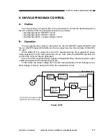
A.
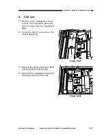
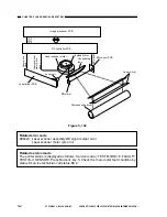
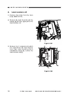
Laser scanner unit
1) Remove the printer from the main
body. (Refer to 9-19)
2) Remove the mylar sheet [1] and the
sponge [2] from the upper part of the
laser scanner unit.
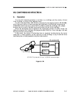
3) Remove the 3 connectors [3] which
are connected to the laser scanner
unit. Then, after removing the 4
installation screws [4], remove the
laser scanner unit [5].
Figure 5-501
Figure 5-502
[2]
[1]
[3]
[5]
[3]
[4]
[4]
Summary of Contents for GP160
Page 6: ...COPYRIGHT 1999 CANON INC CANON GP160 REV 0 FEB 1999 PRINTED IN JAPAN IMPRIME AU JAPON iv ...
Page 12: ......
Page 52: ......
Page 64: ......
Page 74: ......
Page 86: ......
Page 88: ......
Page 98: ......
Page 108: ......
Page 110: ......
Page 146: ......
Page 148: ......
Page 158: ......
Page 186: ......
Page 188: ......
Page 204: ......
Page 206: ......
Page 224: ......
Page 232: ......
Page 234: ......
Page 430: ......
Page 432: ......
Page 434: ...A 2 COPYRIGHT 1999 CANON INC CANON GP160 REV 0 FEB 1999 PRINTED IN JAPAN IMPRIME AU JAPON ...
Page 436: ......
Page 482: ......
Page 622: ......
Page 623: ......
Page 625: ......
Page 627: ......
Page 635: ......


