


COPYRIGHT © 1999 CANON INC. CANON GP160 REV.0 FEB. 1999 PRINTED IN JAPAN (IMPRIME AU JAPON)
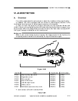
CHAPTER 7 PICK-UP/FEEDING SYSTEM
7-27
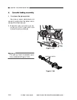
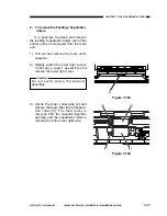
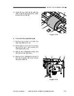
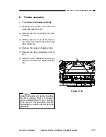
6) Remove the E-ring [9], then remove
the vertical path clutch [10] and the
registration roller clutch [11] (is it not
necessary to remove the clutch con-
nectors).
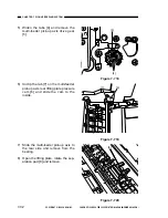
7) Remove the connector [12] and relay
connector [13] from the DC controller
PCB (printer unit rear side). Remove
the disconnected cable from the cord
guide.
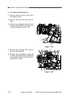
8) Remove the installation screw [14]
and remove the earth plate spring
[15].
9) Remove the installation screw [16],
and then remove the printer unit sup-
port roller [17].
10) Remove the tension spring from the
rear side printer unit pressure lever
[18], then slightly slide the pressure
lever together with the axis.
Figure 7-707
Figure 7-708
Figure 7-709
[11]
[9]
[10]
[9]
[12]
[13]
[18]
[16]
[17]
[14]
[15]
Summary of Contents for GP160
Page 6: ...COPYRIGHT 1999 CANON INC CANON GP160 REV 0 FEB 1999 PRINTED IN JAPAN IMPRIME AU JAPON iv ...
Page 12: ......
Page 52: ......
Page 64: ......
Page 74: ......
Page 86: ......
Page 88: ......
Page 98: ......
Page 108: ......
Page 110: ......
Page 146: ......
Page 148: ......
Page 158: ......
Page 186: ......
Page 188: ......
Page 204: ......
Page 206: ......
Page 224: ......
Page 232: ......
Page 234: ......
Page 430: ......
Page 432: ......
Page 434: ...A 2 COPYRIGHT 1999 CANON INC CANON GP160 REV 0 FEB 1999 PRINTED IN JAPAN IMPRIME AU JAPON ...
Page 436: ......
Page 482: ......
Page 622: ......
Page 623: ......
Page 625: ......
Page 627: ......
Page 635: ......


