


COPYRIGHT © 1999 CANON INC. CANON GP160 REV.0 FEB. 1999 PRINTED IN JAPAN (IMPRIME AU JAPON)
CHAPTER 5 LASER EXPOSURE SYSTEM
5-4
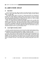
III. LASER DRIVER CIRCUIT
A.
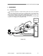
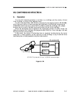
Operation
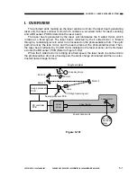
This circuit turns the laser diode (LD) ON at a fixed light intensity. The fixed beam is
based on a video signal (VDO*, VDO) which is sent from the image processor PCB via
the DC controller PCB.
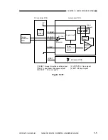
The binarised image signal is converted to a VDO signal with the low amplitude dif-
ferential VDO* signal, inside the image processor PCB, and sent to the DC controller
PCB. Then, it is sent unchanged to the laser driver PCB receiver. The receiver returns
the low amplitude differential signal to its original form and sends it as a video out signal
(VDOUT* signal) to the logic circuit inside the laser driver.
When the image formation enabling signal (ENBL*) from the DC controller PCB
(IC30) is “0”, the laser driver PCB, turns the laser diode ON/OFF in accordance with the
VDOUT* signal. Furthermore, when the print resolution is output by 1200 dpi equivalent
or by 600dpi, by changing the laser light intensity switching signal (600*), the laser light
intensity can be altered. By changing the laser light intensity switching signal to “1” when
1200 dpi equivalent, and to “0” when 600pdi equivalent, the laser light intensity is
switched by the laser driver IC power adjustment circuit.
B.
Laser light intensity control
The laser (semiconductor laser) has the characteristic that the light intensity will fluc-
tuate greatly when the ambient temperature changes. Therefore, the laser drive current
is controlled to change automatically with the changes in the light intensity.
When the laser diode emits light, the laser elements built-in photo-diode receives the
laser beam, and returns the received light output voltage, which corresponds to the
strength of the light intensity, to the laser driver IC control amplifier circuit. At the control
amplifier circuit, the electrical current which was set at the photo diode output voltage
and the power adjustment circuit is compared, and the electrical current flow to the laser
diode is controlled. This laser control takes place constantly during laser beam emis-
sion.
Summary of Contents for GP160
Page 6: ...COPYRIGHT 1999 CANON INC CANON GP160 REV 0 FEB 1999 PRINTED IN JAPAN IMPRIME AU JAPON iv ...
Page 12: ......
Page 52: ......
Page 64: ......
Page 74: ......
Page 86: ......
Page 88: ......
Page 98: ......
Page 108: ......
Page 110: ......
Page 146: ......
Page 148: ......
Page 158: ......
Page 186: ......
Page 188: ......
Page 204: ......
Page 206: ......
Page 224: ......
Page 232: ......
Page 234: ......
Page 430: ......
Page 432: ......
Page 434: ...A 2 COPYRIGHT 1999 CANON INC CANON GP160 REV 0 FEB 1999 PRINTED IN JAPAN IMPRIME AU JAPON ...
Page 436: ......
Page 482: ......
Page 622: ......
Page 623: ......
Page 625: ......
Page 627: ......
Page 635: ......


