


COPYRIGHT © 1999 CANON INC. CANON GP160 REV.0 FEB. 1999 PRINTED IN JAPAN (IMPRIME AU JAPON)
CHAPTER 4 IMAGE PROCESSING SYSTEM
4-2
II. ANALOG IMAGE PROCESSING
A.
Overview
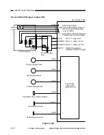
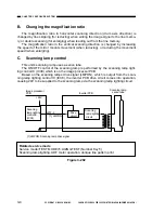
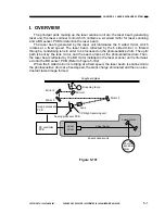
The analog processor PCB converts the CCD drive control and CCD output signals
(analog signals) into digital signals. It also controls the AE.
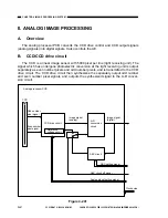
B.
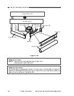
CCD/CCD drive circuit
The CCD is a linear image sensor with 5000 pixel per line (light receiving unit). The
signal which has undergone photoelectric conversion at the light receiving unit is output
separately as even number pixels and odd number pixels, and is transmitted to the CCD
drive circuit. The CCD drive circuit then synthesizes the separately output odd number
and even number pixel signals, and outputs the synthesized signal to the A-D conver-
sion circuit.
Figure 4-201
CCD
CCD drive circuit
A-D
conversion
circuit
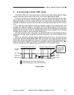
ABC circuit
Reference
voltage circuit
Odd number
pixel signal
Even number
pixel signal
Image signal
(analog)
Image signal
(digital)
ABC circuit off signal
Analog signal setting signal
ABC setting signal
Analog processor PCB
Clock pulse
Summary of Contents for GP160
Page 6: ...COPYRIGHT 1999 CANON INC CANON GP160 REV 0 FEB 1999 PRINTED IN JAPAN IMPRIME AU JAPON iv ...
Page 12: ......
Page 52: ......
Page 64: ......
Page 74: ......
Page 86: ......
Page 88: ......
Page 98: ......
Page 108: ......
Page 110: ......
Page 146: ......
Page 148: ......
Page 158: ......
Page 186: ......
Page 188: ......
Page 204: ......
Page 206: ......
Page 224: ......
Page 232: ......
Page 234: ......
Page 430: ......
Page 432: ......
Page 434: ...A 2 COPYRIGHT 1999 CANON INC CANON GP160 REV 0 FEB 1999 PRINTED IN JAPAN IMPRIME AU JAPON ...
Page 436: ......
Page 482: ......
Page 622: ......
Page 623: ......
Page 625: ......
Page 627: ......
Page 635: ......


