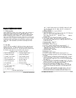
17
Host Data 0
18
Host Data 15
19
Ground
20
No
Connect
21
DRQ 0
22
Ground
23
Host IOW
24
Ground
25
Host IOR
26
Ground
27
IOCHRDY
28
Host ALE
29
DACK 0
30
Ground
31
IRQ 14
32
No Connect
33
Address 1
34
No Connect
35
Address 0
36
Address 2
37
Chip Select 0
38
Chip Select 1
39
Activity
40
Ground
y
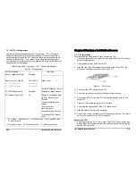
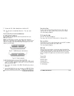
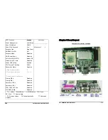
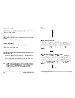
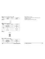
Figure:
ID E 1
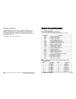
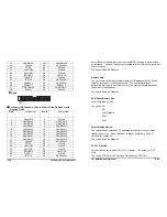
Secondary IDE Connector (44-pin 2.00mm Pitch Pin-Header with
Housing):
IDE2
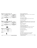
Pin #
Assignment
Pin #
Assignment
1
Reset IDE
2
Ground
3
Host Data 7
4
Host Data 8
5
Host Data 6
6
Host Data 9
7
Host Data 5
8
Host Data 10
9
Host Data 4
10
Host Data 11
11
Host Data 3
12
Host Data 12
13
Host Data 2
14
Host Data 13
15
Host Data 1
16
Host Data 14
17
Host Data 0
18
Host Data 15
19
Ground
20
No
Connect
21
DRQ 1
22
Ground
23
Host IOW
24
Ground
25
Host IOR
26
Ground
27
IOCHRDY
28
Host ALE
29
DACK 1
30
Ground
31
IRQ 15
32
No Connect
15” Panel PC User’s Manual
P43
Select “Enabled” allows caching of the video BIOS, resulting in better system
performance. However, if any program writes to this memory area, a system
error may result.
The choice: Enabled, Disabled.
Memory Hole:
You can reserve this area of system memory for ISA adapter ROM. When
this area is reserved, it cannot be cached. The user information of
peripherals that need to use this area of system memory usually discusses
their memory requirements.
The choice: Enabled, Disabled.
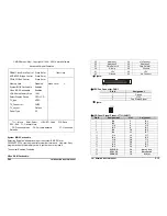
VGA Share Memory Size:
Select VGA memory size.
The choice: 4M
8M
16M (Default)
32M
64M
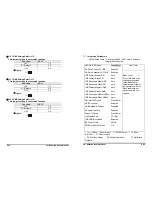
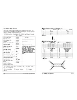
Select Display Device:
The chipset has an embedded 32-bit posted write buffer to support delay
transactions cycles. Select “Enabled” to support compliance with PCI
specification version 2.1.
The choice: Enabled, Disabled.
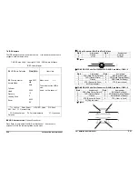
CRT LCD Switch:
This item allows you to select CRT or LCD display. The default is “CRT
Only”.
The choice: LCD Only, CRT Only and Simultaneous, CRT Only.
P14
15” Panel PC User’s Manual

