


15” Panel PC User’s Manual
P51
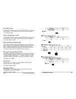
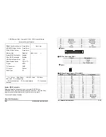
Power On by Ring:
2. To remove the CPU, lift the releasing lever of the Socket 370.
An input signal on the serial Ring Indicator (RI) line (in other words, an
incoming call on the modem) awakens the system from a soft off state.
Note: The CPU and the heat radiation plate are hot. They may cause
burns.
The choice: Enabled, Disabled.
To remove the CPU, reverse the installation steps.
CPU Thermal-Throttling:
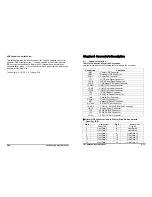
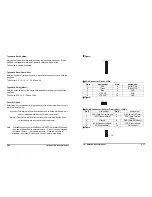
2-2 Memory Module Installation
Select the CPU THRM-Throttling rate.
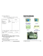
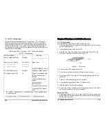
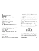
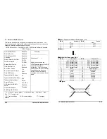
Figure 5 display the notch marks and what they should look like on your
DIMM memory module.
The choice: 12.5%, 25.0%, 37.5%, 50.0%, 62.5%, 75.0% and 87.5%.
DIMMs have184-pins and two notches, that will match with the onboard
DIMM socket. DIMM modules are installed by placing the chip firmly into the
socket at a 90-degree angle and pressing straight down (figure 6) until it fits
tightly into the DIMM socket.
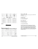
Resume by Alarm:
When “Enabled”, your can set the date and time at which the RTC (real-time
clock) alarm awakens the system from Suspend mode.
The choice: Enabled, Disabled.
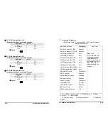
PM Events:
PM events are I/O events whose occurrence can prevent the system from
entering a power saving mode or can awaken the system from such a mode.
In effect, the system remains alert for anything, which occurs to a device,
which is configured as Enabled, even when the system is in a power down
mode.
Figure 5: DIMM Memory and 184-pins Socket
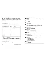
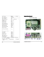
Primary IDE 0
Primary IDE 1
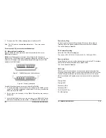
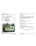
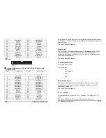
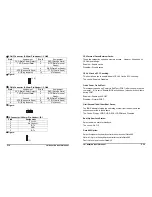
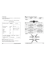
Figure 6: Memory Installation
Secondary IDE 0
Carefully follow the steps below in order to install the DIMMs:
Secondary IDE 1
1. To avoid generating static electricity and damaging the DIMM, ground
yourself by touching a grounded metal surface or using a ground scrap
before you touch the DIMM.
FDD, COM, LPT Port
PCI PIRQ [A-D] #
2. Do not touch the connector of the DIMM. Dirt residue may cause a
malfunction.
3. Hold the DIMM with its notch to the front side of the NASA-6822 Series
and insert it completely into the socket. A DIMM should be inserted into
P6
15” Panel PC User’s Manual