Avalue Technology ARC-1532-C1, Quick Reference Manual
The Avalue Technology ARC-1532-C1 is a high-performance device designed for efficient computing. To understand its features and functions quickly, download the free Quick Reference Manual from our website. This manual is packed with useful information for easy setup and usage. Get your free download at manualshive.com now.
Share
Download


Reviews:
No comments
Related manuals for ARC-1532-C1

SOLAR PANEL
Brand: Waka Waka Pages: 2

151FD - PRO - 60" Plasma TV
Brand: Pioneer Pages: 167

ARP3476
Brand: Pioneer Pages: 201

KronoMeet KT-1010SC
Brand: Kramer Pages: 2
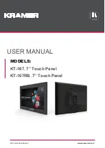
KT-107
Brand: Kramer Pages: 41

Vitovolt 100 RA1
Brand: Viessmann Pages: 16

Vitosol-F Series
Brand: Viessmann Pages: 32

BS2A
Brand: Viessmann Pages: 40

EL 103 ECO
Brand: Lenze Pages: 84

NS-46E440NA14
Brand: Insignia Pages: 91

VICPAS C70 Series
Brand: B&R Pages: 108

32LB9D Series
Brand: LG Pages: 52

32LC7D Series
Brand: LG Pages: 112

V651-TOUCH
Brand: NEC Pages: 2

5070 Series
Brand: Samsung Pages: 111

540
Brand: Samsung Pages: 137

5+ SERIES
Brand: Samsung Pages: 201

5003 Series
Brand: Samsung Pages: 2


