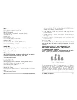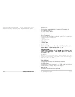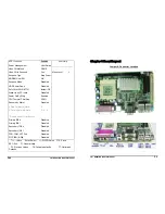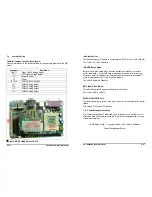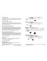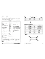
J12 COM1 Setting Select: J12
This jumper setting is secect pin9 function.
Function
JP11
+5V
1-2
RI (Default)
3-4
+12V
5-6
y
Figure:
J1 2
1
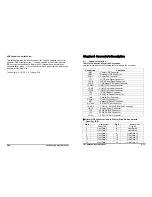
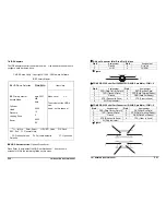
J13 COM3 Setting Select: J13
This jumper setting is secect pin9 function.
Function
JP11
+5V
1-2
RI (Default)
3-4
+12V
5-6
y
Figure:
J1 3
1
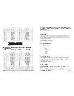
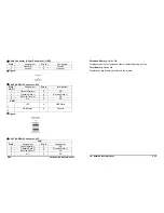
J14 COM2 Setting Select: J14
This jumper setting is secect pin9 function.
Function
JP11
+5V
1-2
RI (Default)
3-4
+12V
5-6
y
Figure:
1
J1 4
15” Panel PC User’s Manual
P45
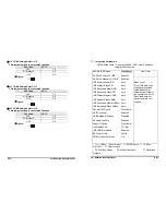
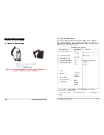
7-7 Integrated
Peripherals
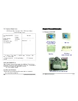
CMOS Setup Utility – Copyright © 1984 – 2001 Award Software
Integrated Peripherals
OnChip IDE Device
On-Chip Primary PCI IDE
On-Chip Secondary PCI IDE
IDE Primary Master PIO
IDE Primary Slave PIO
IDE Secondary Master PIO
IDE Secondary Slave PIO
IDE Primary Master UDMA
IDE Primary Slave UDMA
IDE Secondary Master UDMA
IDE Secondary Slave UDMA
OnChip PCI Device
USB Controller
USB Keyboard Support
Onboard Lan Chip
Super IO Device
Init Display First
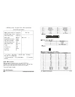
IDE HDD Block Mode
KBC Input Clock
PWRON After PWR-Fail
Press Enter
Enabled
Enabled
Auto
Auto
Auto
Auto
Auto
Auto
Auto
Auto
Press Enter
Enabled
Disabled
Enabled
Press Enter
PCI Slot
Enabled
8MHz
Off
Item Help
____________________
Menu Level
¾
If your IDE hard drive
supports block mode
select Enabled for
automatic detection of
the optimal number of
block read/write per
sector the drive can
support
↑↓←→
Move Enter: Select +/-/PU/PD: Value F10: Save
ESC: Exit F1: General Help
F5: Previous Values F6: Fail-safe defaults F7: Optimized
Defaults
P12
15” Panel PC User’s Manual

