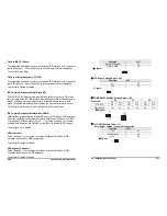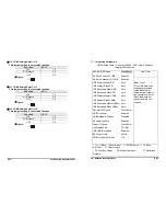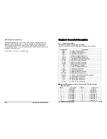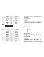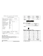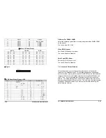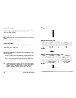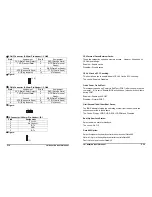
DPMS:
Initial display power management signaling.
Video Off In Suspend:
This determines the manner in which the monitor is blanked.
The choice: Yes, No.
Suspend Type:
Select the Suspend Type.
The choice: PWRON Suspend, Stop Grant.
MODEM Use IRQ:
This determines the IRQ in which the MODEM can use.
The choice: 3, 4, 5, 7, 9, 10, 11 and NA.
Suspend Mode:
When “Enabled” and after the set time of system inactivity. All devices
except the CPU will be shut off.
The choice: Enabled, Disabled.
HDD Power Down:
When “Enabled” and after the set time of system inactivity, the hard disk drive
will be powered down while all other devices remain active.
The choice: Enabled, Disabled.
Soft-Off by PWR-BTTN:
Pressing the power button for more than 4 seconds forces the system to
enter the Soft-Off state when the system has “hung.”
The choice: Delay 4 Sec, Instant-Off.
Wake-Up by PCI Card:
An input signal from PME on the PCI card awakens the system from a soft off
state.
The choice: Enabled, Disabled.
15” Panel PC User’s Manual
P7
the inner socket first. Guiding the hole at each end of the DIMM over the
retaining post at each end of the DIMM socket.
4. If you install two DIMMs, install the second DIMM using the same
procedure as above.
5. If DIMM does not go in smoothly, do not force it. Pull it all the way out
and try again.
6. Make sure the DIMM is properly installed and locked by the tabs on both
sides of the socket.
Removing a DIMM:
To remove the DIMM, use your fingers or a small screwdriver to carefully
push away the plastic tabs that secure the DIMM at each end. Lift it out of
the socket.
Make sure you store the DIMM in an anti-static bag and must be
populated the same size and manufactory of memory modules. .
2-3 Setting Jumpers and DIP Switches
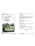
There are jumpers and DIP-switches on the system board of the NASA-6822
Series. You can set the jumpers to make the necessary operations.
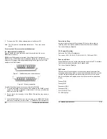
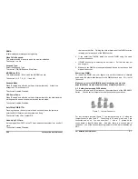
Figure 7: Jumper Connector
For any three-pin jumpers (figure 7), the jumper setting is 1-2 when the
jumper connects pins 1 and 2. The setting is 2-3 when pins 2 and 3 are
connected and so on. You see a number “ 1 “ and a “ 3 “ printed on the
circuit board to identify these pins. And also, there is a second way of
indication – one of the lines surrounding jumpers is thick, which indicates pin
NO.1.
P50
15” Panel PC User’s Manual


