46
| English
2 609 141 101 • 23.7.13
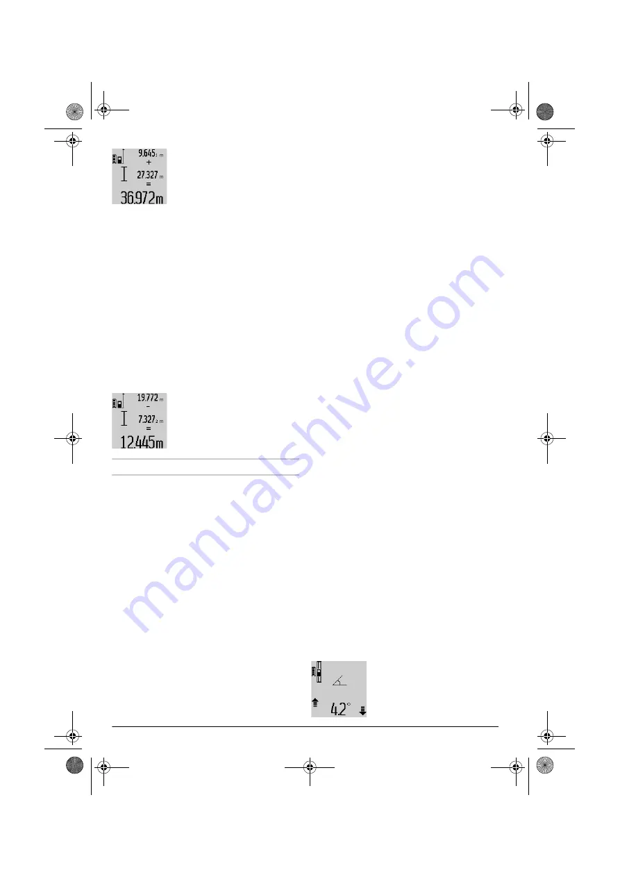
To call up the sum of both meas-
urements, press the result button
6
. The calculation is indicated in
the measured-value lines
a
, and
the sum in the result line
c
.
After calculation of the sum, further measured val-
ues or measured-value list entries can be added to
this result when pressing the plus button
11
prior
to each measurement. Pressing the result button
6
ends the addition.
Notes on the addition:
– Mixed length, area and volume values cannot be
added together. For example, when a length and
area value are added,
“ERROR”
briefly appears
on the display after pressing the result button
6
.
Afterwards, the measuring tool switches back to
the last active measuring mode.
– For each calculation, the result of one measure-
ment is added (e.g. the volume value); for con-
tinuous measurements, this would be the dis-
played measured value in result line
c
. The
addition of individual measured values from the
measured-value lines
a
is not possible.
Subtracting Measured Values
To subtract measuring values,
press minus button
5
; For confir-
mation,
“–”
is indicated on the dis-
play. The further procedure is
analog to “Adding Measured Val-
ues”.
Working Advice
General Information
The reception lens
17
and the laser beam outlet
16
must not be covered when taking a measurement.
The measuring tool must not be moved while tak-
ing a measurement (with the exception of the con-
tinuous measurement and grade measurement
functions). Therefore, place the measuring tool, as
far as this is possible, against or on a firm stop or
supporting surface.
Influence Effects on the Measuring Range
The measuring range depends upon the light con-
ditions and the reflection properties of the target
surface. For improved visibility of the laser beam
when working outdoors and when the sunlight is in-
tense, use laser viewing glasses and laser target
plate, or shade off the target surface.
Influence Effects on the Measuring Result
Due to physical effects, faulty measurements can-
not be excluded when measuring on different sur-
faces. Included here are:
– Transparent surfaces (e.g., glass, water),
– Reflecting surfaces (e.g., polished metal, glass),
– Porous surfaces (e.g. insulation materials),
– Structured surfaces (e.g., roughcast, natural
stone).
If required, use a laser target plate on these surfac-
es.
Furthermore, faulty measurements are also possi-
ble when sighting inclined target surfaces.
Also, air layers with varying temperatures or indi-
rectly received reflections can affect the measured
value.
Accuracy Check and Calibration of the Grade
Measurement (see figure H)
Regularly check the accuracy of the grade meas-
urement. This is done by carrying out a reversal
measurement. For this, place the measuring tool
on a table and measure the grade. Turn the meas-
uring tool by 180 ° and measure the grade again.
The difference of the indicated reading may not ex-
ceed by more than 0.3 ° (max.).
In case of greater deviation, the measuring tool
must be recalibrated. For this, press and hold the
grade measurement button
3
. Follow the directions
on the display.
Accuracy Check of the Distance Measurement
The accuracy of the distance measurement can be
checked as follows:
– Select a permanently unchangeable measuring
section with a length of approx. 1 to 10 metres;
its length must be precisely known (e.g. the
width of a room or a door opening). The measur-
ing distance must be indoors; the target surface
for the measurement must be smooth and reflect
well.
– Measure the distance 10 times after another.
The deviation of the individual measurements from
the mean value must not exceed ± 2 mm (max.).
Log the measurements, so that you can compare
their accuracy at a later point of time.
Working with the Tripod
The use of a tripod is particularly necessary for
larger distances. The measuring tool can be
screwed onto a commercially available tripod using
the 1/4" thread
19
on the bottom side of the hous-
ing.
Set the corresponding reference level for measure-
ment with a tripod by pushing button
10
(the refer-
ence level is the thread).
Working with the Measuring Rail
(see figures I–K)
The measuring rail
24
can be used for a more ac-
curate grade measurement result. Distance meas-
urements are not possible with the measuring rail.
Place the measuring tool into the
measuring rail
24
as shown and
lock the measuring tool with lock-
ing lever
25
. Press the measuring
button
2
to activate the “Measuring
rail” operating mode.
OBJ_BUCH-1840-002.book Page 46 Tuesday, July 23, 2013 3:52 PM


