


MFC-8440/8840D/8840DN, DCP-8040/8045D/8045DN
SERVICE MANUAL
4-1
CHAPTER 4 DISASSEMBLY AND RE-ASSEMBLY
1. SAFETY PRECAUTIONS
To avoid creating secondary problems by mishandling, follow the warnings and precautions below
during maintenance work.
WARNING
(1) Always turn off the power switch and unplug the power cord from the power outlet
before accessing any parts inside the printer.
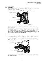
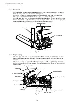
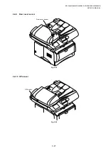
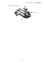
(2) Some parts inside the printer are extremely hot immediately after the printer is
used. When opening the front cover or rear cover to access any parts inside the
printer, never touch the red colored parts shown in the following figures.
!
CAUTION:
(1) Be careful not to lose screws, washers, or other parts removed.
(2) Be sure to apply grease to the gears and applicable positions specified in this chapter.
(3) When using soldering irons or other heat-generating tools, take care not to accidentally damage
parts such as wires, PCBs and covers.
(4) Static electricity charged in your body may damage electronic parts. When transporting PCBs, be
sure to wrap them in conductive sheets.
(5) When replacing the PCB and all the other related parts, put on a grounding wrist band and perform
the job on a static mat. Also take care not to touch the conductor sections on the flat cables or on
the wire harness.
(6) Be sure to replace self-tapping screws correctly, if removed. Unless otherwise specified, tighten
screws to the following torque values.
TAPTITE, BIND or CUP B
M3:
0.7N
y
m
M4:
0.8N
y
m
TAPTITE, CUP S
M3:
0.8N
y
m
SCREW
M3:
0.7N
y
m
M4:
0.8N
y
m
(7) After disconnecting flat cables, check that each cable is not damaged at its end or short-circuited
.
(8) When connecting flat cables, do not insert them at an angle. After insertion, check that the cables
are not at an angle.
(9) When connecting or disconnecting cable connectors, hold the connector body, not the cables. If
the connector has a lock, release the connector lock first to release it.
(10) After a repair, check not only the repaired portion but also all connectors. Also check that other
related portions are functioning properly before operational checks.
Summary of Contents for DCP-8040
Page 276: ...CHAPTER 7 MAINTENANCE MODE 7 6 Fig 7 3 l m a b c d e f g h i j k ...
Page 347: ...APPENDIX 4 CIRCUIT DIAGRAMS A 50 Appendix 4 1 Main PCB Circuit Diagram 1 7 ...
Page 349: ...APPENDIX 4 CIRCUIT DIAGRAMS A 52 Appendix 4 3 Main PCB Circuit Diagram 3 7 ...
Page 351: ...APPENDIX 4 CIRCUIT DIAGRAMS A 54 Appendix 4 5 Main PCB Circuit Diagram 5 7 ...
Page 353: ...APPENDIX 4 CIRCUIT DIAGRAMS A 56 Appendix 4 7 Main PCB Circuit Diagram 7 7 ...
Page 355: ...APPENDIX 4 CIRCUIT DIAGRAMS A 58 Appendix 4 9 Engine PCB Circuit Diagram 1 2 ...
Page 357: ...APPENDIX 4 CIRCUIT DIAGRAMS A 60 Appendix 4 11 NCU PCB Circuit Diagram U S A ...
Page 359: ...APPENDIX 4 CIRCUIT DIAGRAMS A 62 Appendix 4 13 NCU PCB Circuit Diagram Asia ...
Page 361: ...APPENDIX 4 CIRCUIT DIAGRAMS A 64 Appendix 4 15 Control Panel PCB Circuit Diagram ...
Page 367: ...April 04 SM FAX027 5 8C5903 Printed in Japan ...