


CHAPTER 7 MAINTENANCE MODE
7-10
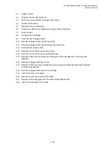
WSW No.
Function
WSW35
Function setting 13
WSW36
Function setting 14
WSW37
Function setting 15
WSW38
Function setting 16
WSW39
Function setting 17
WSW40
Function setting 18
WSW41
Function setting 19
WSW42
Function setting 20
WSW43
Function setting 21
WSW44
Speeding up scanning-1
WSW45
Speeding up scanning-2
WSW46
Monitor of PC ON/OFF state
WSW47
Function setting 22
WSW48
Function setting 23
WSW49
Function setting 24
WSW50 Not
used.
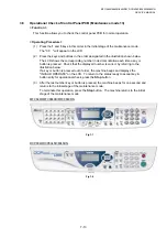
< Operating Procedure >
(1) Press
the
1
and
0
keys in this order in the initial stage of the maintenance mode.
The machine displays the "WSW00" on the LCD and becomes ready to accept a
firmware switch number.
(2) Enter the desired number from the firmware switch numbers (01 through 50).
The following appears on the LCD:
Selector 1 Selector 8
↓
↓
WSWXX =
0 0 0 0 0 0 0 0
(3) Use
the and
keys to move the cursor to the selector position to be modified.
(4) Enter a value to be set (0 or 1) using the
0
and
1
keys.
(5) Press
the
Set
button. This operation saves the newly entered selector values onto the
EEPROM and readies the machine for accepting a firmware switch number.
(6) Repeat steps (2) through (5) until the modification for the desired firmware switches is
completed.
(7) Press
the
Stop
button to return the machine to the initial stage of the maintenance
mode.
NOTE:
•
To cancel this operation and return the machine to the initial stage of the maintenance
mode during the above procedure, press the
Stop
button.
•
If there is a pause of more than one minute after a single-digit number is entered for
double-digit firmware switch numbers, the machine will automatically return to the initial
stage of the maintenance mode.
< Details of Firmware Switches >
•
The details of the firmware switches are described in
Appendix 3
in which the user-
accessible selectors of the firmware switches are shaded.
•
Machine w/o fax support some selectors of firmware switches. Those selector numbers
are circled.
Summary of Contents for DCP-8040
Page 276: ...CHAPTER 7 MAINTENANCE MODE 7 6 Fig 7 3 l m a b c d e f g h i j k ...
Page 347: ...APPENDIX 4 CIRCUIT DIAGRAMS A 50 Appendix 4 1 Main PCB Circuit Diagram 1 7 ...
Page 349: ...APPENDIX 4 CIRCUIT DIAGRAMS A 52 Appendix 4 3 Main PCB Circuit Diagram 3 7 ...
Page 351: ...APPENDIX 4 CIRCUIT DIAGRAMS A 54 Appendix 4 5 Main PCB Circuit Diagram 5 7 ...
Page 353: ...APPENDIX 4 CIRCUIT DIAGRAMS A 56 Appendix 4 7 Main PCB Circuit Diagram 7 7 ...
Page 355: ...APPENDIX 4 CIRCUIT DIAGRAMS A 58 Appendix 4 9 Engine PCB Circuit Diagram 1 2 ...
Page 357: ...APPENDIX 4 CIRCUIT DIAGRAMS A 60 Appendix 4 11 NCU PCB Circuit Diagram U S A ...
Page 359: ...APPENDIX 4 CIRCUIT DIAGRAMS A 62 Appendix 4 13 NCU PCB Circuit Diagram Asia ...
Page 361: ...APPENDIX 4 CIRCUIT DIAGRAMS A 64 Appendix 4 15 Control Panel PCB Circuit Diagram ...
Page 367: ...April 04 SM FAX027 5 8C5903 Printed in Japan ...