


MFC-8440/8840D/8840DN, DCP-8040/8045D/8045DN
SERVICE MANUAL
4-57
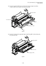
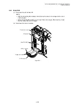
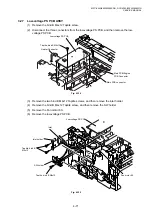
(10) Remove the two pan (washer) M2.6x6 Taptite screws.
(11) Remove the heat roller 25.
(12) Remove the halogen lamp.
Fig. 4-101
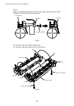
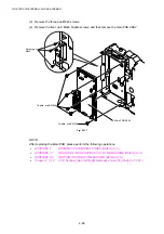
NOTE:
When re-assembling the halogen heater lamp, ensure that the direction of the halogen heater
lamp is correct referring to the figure above.
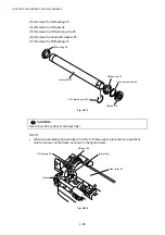
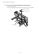
!
CAUTION:
•
Never touch the surface of the halogen heater lamp.
•
When securing the screw to assemble the halogen lamp connector plate, ensure you use
the Fu lamp assembly jig ASSY as shown in the figure below to avoid damaging the edge
of the halogen heater lamp.
Fig. 4-102
Screw, pan (washer) M2.6x6
Fu lamp assembly jig ASSY
Halogen lamp connector plate
Halogen heater lamp
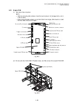
Screw, pan
(washer) M2.6x6
Heat roller 25
FU frame upper
Heat roller 25
Halogen lamp
Halogen lamp
connector plate
Screw, pan (washer)
M2.6x6
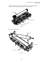
Halogen lamp
Colored side
115V:Orange
230V:Black
Washer 26
Washer 26
Washer 26
Summary of Contents for DCP-8040
Page 276: ...CHAPTER 7 MAINTENANCE MODE 7 6 Fig 7 3 l m a b c d e f g h i j k ...
Page 347: ...APPENDIX 4 CIRCUIT DIAGRAMS A 50 Appendix 4 1 Main PCB Circuit Diagram 1 7 ...
Page 349: ...APPENDIX 4 CIRCUIT DIAGRAMS A 52 Appendix 4 3 Main PCB Circuit Diagram 3 7 ...
Page 351: ...APPENDIX 4 CIRCUIT DIAGRAMS A 54 Appendix 4 5 Main PCB Circuit Diagram 5 7 ...
Page 353: ...APPENDIX 4 CIRCUIT DIAGRAMS A 56 Appendix 4 7 Main PCB Circuit Diagram 7 7 ...
Page 355: ...APPENDIX 4 CIRCUIT DIAGRAMS A 58 Appendix 4 9 Engine PCB Circuit Diagram 1 2 ...
Page 357: ...APPENDIX 4 CIRCUIT DIAGRAMS A 60 Appendix 4 11 NCU PCB Circuit Diagram U S A ...
Page 359: ...APPENDIX 4 CIRCUIT DIAGRAMS A 62 Appendix 4 13 NCU PCB Circuit Diagram Asia ...
Page 361: ...APPENDIX 4 CIRCUIT DIAGRAMS A 64 Appendix 4 15 Control Panel PCB Circuit Diagram ...
Page 367: ...April 04 SM FAX027 5 8C5903 Printed in Japan ...