


CHAPTER 6 TROUBLESHOOTING
6-54
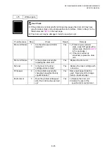
9. INCORRECT PRINTOUT
When the data is not printed correctly as it is seen on the PC screen, follow the procedures
below in the event of a specific error.
P-1
The machine prints unexpectedly or it prints garbage.
User Check
(1) Check if the printer cable is not too long. It is recommended to use a parallel cable of less than 2
meters (6.6 feet) in length.
(2) Check that the printer cable is not damaged or broken. Check also that the printer cable is
connected to the correct interface connectors of both the machine and PC.
(3) If an interface switching device is used, remove it and connect the computer directly to the
machine and try again.
(4) Check that the appropriate printer driver is selected as ‘Set as Default’. Check also that the
correct print port is set for the selected printer driver.
(5) Check that the machine is not connected to the same port which is also connected to a mass
storage device or scanner. Remove all other devices and connect the port to the machine only.
Turn off the printer status monitor in the device options tab in the printer driver.
(6) If the print port is set as an ECP port, change it to a normal port.
(7) Try printing the test page referring to
3.5 ‘Test Pattern 1’ in Chapter 7
(8) Try resetting the factory settings.
Possible cause
Step
Check
Result
Remedy
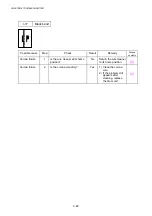
Failure inside
the machine
1
Is it possible to print the test
page with the method of
No
Identify the error type, then
refer to the specified section of
this chapter.
Summary of Contents for DCP-8040
Page 276: ...CHAPTER 7 MAINTENANCE MODE 7 6 Fig 7 3 l m a b c d e f g h i j k ...
Page 347: ...APPENDIX 4 CIRCUIT DIAGRAMS A 50 Appendix 4 1 Main PCB Circuit Diagram 1 7 ...
Page 349: ...APPENDIX 4 CIRCUIT DIAGRAMS A 52 Appendix 4 3 Main PCB Circuit Diagram 3 7 ...
Page 351: ...APPENDIX 4 CIRCUIT DIAGRAMS A 54 Appendix 4 5 Main PCB Circuit Diagram 5 7 ...
Page 353: ...APPENDIX 4 CIRCUIT DIAGRAMS A 56 Appendix 4 7 Main PCB Circuit Diagram 7 7 ...
Page 355: ...APPENDIX 4 CIRCUIT DIAGRAMS A 58 Appendix 4 9 Engine PCB Circuit Diagram 1 2 ...
Page 357: ...APPENDIX 4 CIRCUIT DIAGRAMS A 60 Appendix 4 11 NCU PCB Circuit Diagram U S A ...
Page 359: ...APPENDIX 4 CIRCUIT DIAGRAMS A 62 Appendix 4 13 NCU PCB Circuit Diagram Asia ...
Page 361: ...APPENDIX 4 CIRCUIT DIAGRAMS A 64 Appendix 4 15 Control Panel PCB Circuit Diagram ...
Page 367: ...April 04 SM FAX027 5 8C5903 Printed in Japan ...