


CHAPTER 5 PERIODIC MAINTENANCE
5-22
3. PERIODICAL CLEANING
Clean the following parts periodically to avoid any machine problems or print image defects.
!
CAUTION:
While drum unit and scanner window cleaning basically can be implemented by the end user,
the electrical terminals inside the machine and on the drum unit should be cleaned by a
service technician. Instruct the users not to touch those terminals.
WARNING
There are high voltage electrodes inside the machine. Before cleaning the machine,
make sure that the power switch has been turned off and the power cord has been
unplugged from the power outlet.
3.1
Cleaning the Machine Exterior
Clean the machine exterior to keep the machine clean.
1) Turn off the power switch and unplug the power cord.
2) Wipe dirt and dust away from the machine exterior with a damp cloth and allow the
machine to dry completely before turning the power on again.
3) Plug in the power cord.
!
CAUTION:
•
Use water or neutral detergents for cleaning. Cleaning with volatile liquids such as thinner
or benzene will damage the surface of the machine.
•
Do not use cleaning materials that contain ammonia. They will damage the machine and
the toner cartridge.
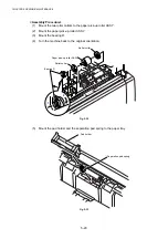
3.2
Cleaning the Scanner
Turn the machine power switch off and lift the document cover. Clean the scanner glass and
glass strip with dry cloth and the white film with isopropyl alcohol on a lint free cloth.
Fig.5-36
White film
Glass strip
Document cover
Summary of Contents for DCP-8040
Page 276: ...CHAPTER 7 MAINTENANCE MODE 7 6 Fig 7 3 l m a b c d e f g h i j k ...
Page 347: ...APPENDIX 4 CIRCUIT DIAGRAMS A 50 Appendix 4 1 Main PCB Circuit Diagram 1 7 ...
Page 349: ...APPENDIX 4 CIRCUIT DIAGRAMS A 52 Appendix 4 3 Main PCB Circuit Diagram 3 7 ...
Page 351: ...APPENDIX 4 CIRCUIT DIAGRAMS A 54 Appendix 4 5 Main PCB Circuit Diagram 5 7 ...
Page 353: ...APPENDIX 4 CIRCUIT DIAGRAMS A 56 Appendix 4 7 Main PCB Circuit Diagram 7 7 ...
Page 355: ...APPENDIX 4 CIRCUIT DIAGRAMS A 58 Appendix 4 9 Engine PCB Circuit Diagram 1 2 ...
Page 357: ...APPENDIX 4 CIRCUIT DIAGRAMS A 60 Appendix 4 11 NCU PCB Circuit Diagram U S A ...
Page 359: ...APPENDIX 4 CIRCUIT DIAGRAMS A 62 Appendix 4 13 NCU PCB Circuit Diagram Asia ...
Page 361: ...APPENDIX 4 CIRCUIT DIAGRAMS A 64 Appendix 4 15 Control Panel PCB Circuit Diagram ...
Page 367: ...April 04 SM FAX027 5 8C5903 Printed in Japan ...