


CHAPTER 6 TROUBLESHOOTING
6-14
!
CAUTION:
To prevent damage to the machine caused by static electricity, do not touch the electrodes
shown in Figure 6-6.
Fig. 6-6
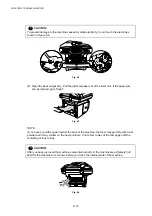
(5) Open the back output tray. Pull the jammed paper out of the fuser unit. If the paper jam
can be cleared, go to Step 7.
Fig. 6-7
NOTE:
If you have to pull the paper toward the back of the machine, the fuser may get dirty with toner
powder and it may scatter on the next printouts. Print a few copies of the test page until the
scattering of toner stops.
!
CAUTION:
After you have just used the machine, some internal parts of the machine are extremely hot!
Wait for the machine to cool down before you touch the internal parts of the machine.
Fig. 6-8
Summary of Contents for DCP-8040
Page 276: ...CHAPTER 7 MAINTENANCE MODE 7 6 Fig 7 3 l m a b c d e f g h i j k ...
Page 347: ...APPENDIX 4 CIRCUIT DIAGRAMS A 50 Appendix 4 1 Main PCB Circuit Diagram 1 7 ...
Page 349: ...APPENDIX 4 CIRCUIT DIAGRAMS A 52 Appendix 4 3 Main PCB Circuit Diagram 3 7 ...
Page 351: ...APPENDIX 4 CIRCUIT DIAGRAMS A 54 Appendix 4 5 Main PCB Circuit Diagram 5 7 ...
Page 353: ...APPENDIX 4 CIRCUIT DIAGRAMS A 56 Appendix 4 7 Main PCB Circuit Diagram 7 7 ...
Page 355: ...APPENDIX 4 CIRCUIT DIAGRAMS A 58 Appendix 4 9 Engine PCB Circuit Diagram 1 2 ...
Page 357: ...APPENDIX 4 CIRCUIT DIAGRAMS A 60 Appendix 4 11 NCU PCB Circuit Diagram U S A ...
Page 359: ...APPENDIX 4 CIRCUIT DIAGRAMS A 62 Appendix 4 13 NCU PCB Circuit Diagram Asia ...
Page 361: ...APPENDIX 4 CIRCUIT DIAGRAMS A 64 Appendix 4 15 Control Panel PCB Circuit Diagram ...
Page 367: ...April 04 SM FAX027 5 8C5903 Printed in Japan ...