


CHAPTER 4 DISASSEMBLY AND RE-ASSEMBLY
4-62
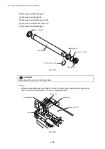
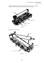
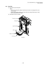
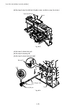
NOTE:
When re-assembling the paper eject actuator and the eject actuator spring to the FU frame
lower, ensure the paper eject actuator is seated correctly in the locating channel referring to
the figure below;
Fig. 4-111
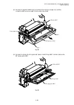
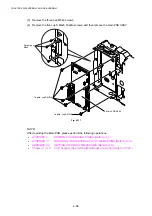
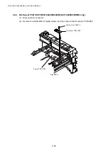
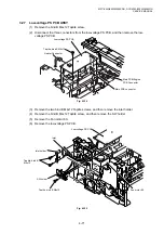
(28) Disconnect the heater harness.
(29) Remove the four cup B M3x6 Taptite screws.
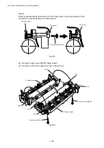
(30) Remove the four claw holder plate.
(31) Remove the four separate claw ASSY.
Fig. 4-112
Paper eject actuator
Eject actuator spring
FU frame lower
Separate claw ASSY
Separate claw ASSY
Heater harness
Claw holder plate
Taptite, cup B M3x6
Tweezers
Summary of Contents for DCP-8040
Page 276: ...CHAPTER 7 MAINTENANCE MODE 7 6 Fig 7 3 l m a b c d e f g h i j k ...
Page 347: ...APPENDIX 4 CIRCUIT DIAGRAMS A 50 Appendix 4 1 Main PCB Circuit Diagram 1 7 ...
Page 349: ...APPENDIX 4 CIRCUIT DIAGRAMS A 52 Appendix 4 3 Main PCB Circuit Diagram 3 7 ...
Page 351: ...APPENDIX 4 CIRCUIT DIAGRAMS A 54 Appendix 4 5 Main PCB Circuit Diagram 5 7 ...
Page 353: ...APPENDIX 4 CIRCUIT DIAGRAMS A 56 Appendix 4 7 Main PCB Circuit Diagram 7 7 ...
Page 355: ...APPENDIX 4 CIRCUIT DIAGRAMS A 58 Appendix 4 9 Engine PCB Circuit Diagram 1 2 ...
Page 357: ...APPENDIX 4 CIRCUIT DIAGRAMS A 60 Appendix 4 11 NCU PCB Circuit Diagram U S A ...
Page 359: ...APPENDIX 4 CIRCUIT DIAGRAMS A 62 Appendix 4 13 NCU PCB Circuit Diagram Asia ...
Page 361: ...APPENDIX 4 CIRCUIT DIAGRAMS A 64 Appendix 4 15 Control Panel PCB Circuit Diagram ...
Page 367: ...April 04 SM FAX027 5 8C5903 Printed in Japan ...