


MFC-8440/8840D/8840DN, DCP-8040/8045D/8045DN
SERVICE MANUAL
4-79
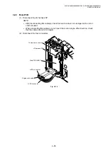
3.29 Frame L / Drive Unit
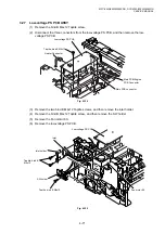
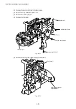
(1) Remove the main PCB sheet from the frame L.
(2) Remove the four bind B M4x12 Taptite screws.
(3) Remove the two bind B M3x10 Taptite screws, and then remove the frame L.
Fig. 4-141
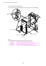
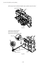
(4) Remove the back up plate ground spring. (DCP-8040/MFC-8440 only)
Fig. 4-142
Taptite, bind B M3x10
Taptite, bind B M3x10
Under bar
Under bar
Main PCB
sheet
Frame L
Frame L
Back up plate
ground spring
Drive unit
Taptite, bind B M4x12
Taptite, bind B M4x12
Summary of Contents for DCP-8040
Page 276: ...CHAPTER 7 MAINTENANCE MODE 7 6 Fig 7 3 l m a b c d e f g h i j k ...
Page 347: ...APPENDIX 4 CIRCUIT DIAGRAMS A 50 Appendix 4 1 Main PCB Circuit Diagram 1 7 ...
Page 349: ...APPENDIX 4 CIRCUIT DIAGRAMS A 52 Appendix 4 3 Main PCB Circuit Diagram 3 7 ...
Page 351: ...APPENDIX 4 CIRCUIT DIAGRAMS A 54 Appendix 4 5 Main PCB Circuit Diagram 5 7 ...
Page 353: ...APPENDIX 4 CIRCUIT DIAGRAMS A 56 Appendix 4 7 Main PCB Circuit Diagram 7 7 ...
Page 355: ...APPENDIX 4 CIRCUIT DIAGRAMS A 58 Appendix 4 9 Engine PCB Circuit Diagram 1 2 ...
Page 357: ...APPENDIX 4 CIRCUIT DIAGRAMS A 60 Appendix 4 11 NCU PCB Circuit Diagram U S A ...
Page 359: ...APPENDIX 4 CIRCUIT DIAGRAMS A 62 Appendix 4 13 NCU PCB Circuit Diagram Asia ...
Page 361: ...APPENDIX 4 CIRCUIT DIAGRAMS A 64 Appendix 4 15 Control Panel PCB Circuit Diagram ...
Page 367: ...April 04 SM FAX027 5 8C5903 Printed in Japan ...