


CHAPTER 7 MAINTENANCE MODE
7-24
3.15
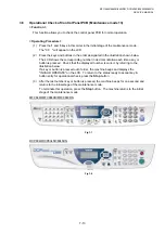
Display of the Equipment’s Log Information (Maintenance mode 80)
< Function >
The equipment may display its log information on the LCD.
< Operating Procedure >
(1) Press
the
8
and
0
keys in this order in the initial stage of the maintenance mode.
The USB serial number appears on the LCD.
(2) Press
the
Start
button. Each time the
Start
button is pressed, one of the following log
information items appears on the LCD in the order given below.
1) Jam count, indicating how many times a paper jam has been occurred
2) Page count, indicating how many pages the photosensitive drum has been printed
3) Total page count, indicating how many pages the equipment has been printed
since produced
4) Drum count, indicating how many times the photosensitive drum has been rotated
5) Drum change count, indicating how many times drum replacement has been
made
6) Toner change count, indicating how many times toner replacement has been
made
7) Copy page count, indicating how many copies have been made
8) PC print page count, indicating how many pages the equipment has been printed
as an output device of the connected PC
9) FAX page count, indicating how many received FAX pages have been printed
10) Error code of the most recent machine error *
1
11) Error code of the most recent communications error *
2
12) ADF jam count, indicating how many times a document jam has been occurred
13) ADF page count, indicating how many documents have been fed
(3) To stop this operation and return to the equipment to the initial stage of the
maintenance mode, press the
Stop
button.
*
1
When you press the
Set
button while the MACHINE ERR error code is displayed,
the last error code is displayed. Each time the
Set
button is pressed, up to the ten
error codes are displayed one by one in reverse order.
*
2
When you press the
Set
button while the COMEER1 error is displayed, the last
error, the previous error, and the second previous error are displayed in turn. The
indication changes from COMEER1, COMEER2, to COMEER3.
Summary of Contents for DCP-8040
Page 276: ...CHAPTER 7 MAINTENANCE MODE 7 6 Fig 7 3 l m a b c d e f g h i j k ...
Page 347: ...APPENDIX 4 CIRCUIT DIAGRAMS A 50 Appendix 4 1 Main PCB Circuit Diagram 1 7 ...
Page 349: ...APPENDIX 4 CIRCUIT DIAGRAMS A 52 Appendix 4 3 Main PCB Circuit Diagram 3 7 ...
Page 351: ...APPENDIX 4 CIRCUIT DIAGRAMS A 54 Appendix 4 5 Main PCB Circuit Diagram 5 7 ...
Page 353: ...APPENDIX 4 CIRCUIT DIAGRAMS A 56 Appendix 4 7 Main PCB Circuit Diagram 7 7 ...
Page 355: ...APPENDIX 4 CIRCUIT DIAGRAMS A 58 Appendix 4 9 Engine PCB Circuit Diagram 1 2 ...
Page 357: ...APPENDIX 4 CIRCUIT DIAGRAMS A 60 Appendix 4 11 NCU PCB Circuit Diagram U S A ...
Page 359: ...APPENDIX 4 CIRCUIT DIAGRAMS A 62 Appendix 4 13 NCU PCB Circuit Diagram Asia ...
Page 361: ...APPENDIX 4 CIRCUIT DIAGRAMS A 64 Appendix 4 15 Control Panel PCB Circuit Diagram ...
Page 367: ...April 04 SM FAX027 5 8C5903 Printed in Japan ...