


APPENDIX 3 FIRMWARE SWITCHS (WSW)
A-46
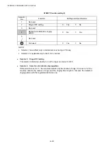
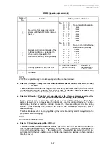
WSW44 (Speeding up scanning-1)
Selector
No.
Function
Setting and Specifications
1
|
5
Not used.
6
|
8
Effective time length of the white level
compensation data obtained
beforehand
No. 6 7 8
0 0 0 : Obtained compensation data
ineffective
0
0
1
: 1
min.
0
1
0
: 3
min.
0
1
1
: 5
min.
1
0
0
:
10
min.
1
0
1
:
15
min.
1
1
0
:
20
min.
1
1
1
:
30
min.
NOTE:
WSW44 is applicable only to models equipped with a flat-bed scanner.
l
Selectors 6 through 8: Effective time length of the white level compensation data obtained
beforehand
If you set documents in the ADF and the document front sensor detects them or if you open
the document tray ASSY and the document tray open sensor detects the open state, then the
controller will make correction of the reference voltage to be applied to white level
compensation for document scanning before the Copy button is pressed.
These selectors determine how long compensation data obtained beforehand will keep
effective.
Summary of Contents for DCP-8040
Page 276: ...CHAPTER 7 MAINTENANCE MODE 7 6 Fig 7 3 l m a b c d e f g h i j k ...
Page 347: ...APPENDIX 4 CIRCUIT DIAGRAMS A 50 Appendix 4 1 Main PCB Circuit Diagram 1 7 ...
Page 349: ...APPENDIX 4 CIRCUIT DIAGRAMS A 52 Appendix 4 3 Main PCB Circuit Diagram 3 7 ...
Page 351: ...APPENDIX 4 CIRCUIT DIAGRAMS A 54 Appendix 4 5 Main PCB Circuit Diagram 5 7 ...
Page 353: ...APPENDIX 4 CIRCUIT DIAGRAMS A 56 Appendix 4 7 Main PCB Circuit Diagram 7 7 ...
Page 355: ...APPENDIX 4 CIRCUIT DIAGRAMS A 58 Appendix 4 9 Engine PCB Circuit Diagram 1 2 ...
Page 357: ...APPENDIX 4 CIRCUIT DIAGRAMS A 60 Appendix 4 11 NCU PCB Circuit Diagram U S A ...
Page 359: ...APPENDIX 4 CIRCUIT DIAGRAMS A 62 Appendix 4 13 NCU PCB Circuit Diagram Asia ...
Page 361: ...APPENDIX 4 CIRCUIT DIAGRAMS A 64 Appendix 4 15 Control Panel PCB Circuit Diagram ...
Page 367: ...April 04 SM FAX027 5 8C5903 Printed in Japan ...