


Digital Video Recorder
Connections and settings | en
23
Bosch Security Systems
User Manual
F01U | 2.0 | 2008.12
Alarm_in_11 11
Alarm
input
11
Alarm_in_12 12
Alarm
input
12
Alarm_in_13 13
Alarm
input
13
Alarm_in_14 14
Alarm
input
14
Alarm_in_15 15
Alarm
input
15
Alarm_in_16 16
Alarm
input
16
Relay1_A
17
Relay 1 output pole 1
Relay2_A
18
Relay 2 output pole 1
Relay3_A
19
Relay 3 output pole 1
Relay4_A
20
Relay 4 output pole 1
Relay5_A
21
Relay 5 output pole 1
Relay6_A
22
Relay 6 output pole 1
Relay7_A
23
Relay 7 output pole 1
Relay8_A
24
Relay 8 output pole 1
System Ground
25
Chassis Ground
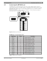
Table 3.3
Alarm I/O pin confi guration
3.11 System
operation
Default monitor setting is VGA.
1.
Turn on the unit. System booting will commence. The BOSCH logo image will be displayed on
the main monitor during the system booting.
2.
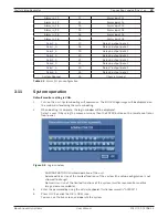
When booting is complete, the login window will be displayed.
Select a user ID by using the mouse or arrow, then the ENTER button on the remote control or
front panel.
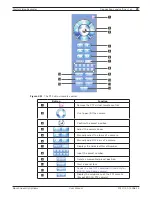
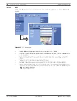
Figure 3.5
Login window
- ADMINISTRATOR: Unlimited operation of the unit.
- Advanced User: Use of the limited functions of the system (the setup confi guration is not
allowed to change).
- Normal User: Use of the limited functions of the system (multiscreen monitor and live
image view are available).
3.
Enter the password by using the virtual keyboard. (Initial password is “000000”.)
4.
Press LOCK or click the OK (LOCK) icon.
You can see the live screen and operate the system.
Summary of Contents for Divar DVR-16K
Page 2: ......
Page 10: ...8 en Safety Digital Video Recorder F01U 2 0 2008 12 User Manual Bosch Security Systems ...
Page 18: ...16 en Introduction Digital Video Recorder F01U 2 0 2008 12 User Manual Bosch Security Systems ...
Page 137: ...Digital Video Recorder Reference en 135 Bosch Security Systems User Manual F01U 2 0 2008 12 ...
Page 138: ...136 en Reference Digital Video Recorder F01U 2 0 2008 12 User Manual Bosch Security Systems ...
Page 139: ......