


ACS 653, ACS 663 Service Manual
SP00D00624
2021-04-08
Robert Bosch GmbH
76
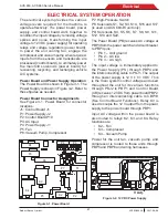
Electrical
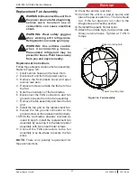
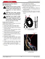
Figure 3-7. High-Pressure Cut-Out Switch
Replacement High-Pressure Cut-Out
Switch
WARNING: Disconnect the unit from the
power source before beginning service
work. Incorrect use or connections can
cause electrical shock.
WARNING: Wear safety goggles
when working with refrigerants.
Refrigerants can cause eye injury.
WARNING: Use extreme caution
when disconnecting hoses.
Pressurized refrigerant may be
present in hoses. Point hoses away
from you and anyone nearby.
Replacement Instructions
Follow these steps to replace the high-pressure
cut-out switch on the unit. See Figure 3-7.
1. Evacuate the unit with a recovery service unit.
2.
Turn off the power switch and disconnect
the unit from the power source.
3. Open the service rear door.
4. Remove the rear cover (above the service
door) by pushing it up and extract it by
pulling it out.
5. Disconnect the wires from the faulty
high-pressure cut-out switch.
6. Carefully remove the faulty cut-out switch.
7.
Clean the fitting by wiping away dirt, grease,
and oil.
NOTE:
DO NOT apply thread sealant to any
internal threads. Apply thread sealant to only
the external pipe threads of the fittings.
8.
Install the new high-pressure cut-out switch.
9. Connect the wires to the new switch.
10. Insert the rear cover so that the 4 holes on
the sides the cover fit into the 4 clips on the
machine. Push down to hook the rear cover.
11. Close the service rear door.
12. Connect the unit to the power source.
13. Operate the unit and check for leaks.
12.
Unit ask for firmware update, press
YES
.
13. Unit ask to RESET the board erasing all the
data and calibrations stored, press
YES
and
please wait. After that service routine starts
with required settings.
14. Select
Languages
and confirm.
15.
Select AC/ACS model (unit require the input
2 times) and confirm.
16. Set
time/date
and confirm.
17. Set
serial number
(unit require the input
2 times). Take the one in the unit data plate
and confirm.
18. Perform air flow calibration (refer to Calibrate
Air Flow in the Diagnostics and Testing
section) and confirm (for R1234yf only).
19. Perform tank calibration (refer to ISV Load
Cell Calibration in the Diagnostics and
Testing section) and confirm.
20. Perform oil calibration (refer to Drain Load
Cell Calibration in the Diagnostics and
Testing section) and confirm.
21. Select
Imperial/Metric
and confirm.
22. Edit
garage data
and confirm.
23. Now unit is ready to install the last encrypted
software present in the USB dongle. If the
dongle is not connected/programmed and
the unit don’t find the software an error
message will be shown on display asking
to retry.
24. The encryption can take several minutes,
the % progress is shown in the display.
25. When unit reboots and displays stand-by
page, please switch unit off and reinstall the
plastic frontal cover (take care to secure the
tank with screws).
26. Attach the outside high- (red) and low-side
(blue) service hoses. Tighten at 7.9 Nm
torque.
27.
Switch on again and repeat air flow calibration
with plastic frontal cover mounted.
28.
Key in the activation code again, using
original serial number the activation code is
still the same. If activation code has been
lost, contact Bosch tech support.
29. Now the unit is ready to use.
NOTE:
All data input not required into procedure
above are already available in the dedicated
software.
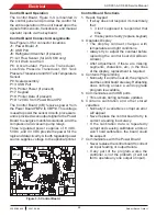
Attach control wires
to these terminals


