ACS 653, ACS 663 Service Manual
SP00D00624
2021-04-08
Robert Bosch GmbH
50
Diagnostics and Testing
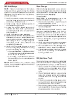
Will Not Fill Tank
NOTE:
The compressor should be running
during this test. If it does not run, refer to
compressor troubleshooting in the Compressor
section of this manual.
1. Verify the low-side service hose is properly
connected and threaded completely onto
the source tank fitting. Check quick-seal on
low-side service hose and make sure virgin
tank valve is open.
2. Is there a message on the display stating
the source tank is empty? If so, verify the
source tank has liquid refrigerant and the
source tank valve is open.
3. Verify the source tank and the tank is
positioned to supply liquid refrigerant to the
low-side service hose. Disposable tanks
should be inverted. Attach the low-side
service hose to the liquid port on a refillable
tank.
NOTE:
The recover solenoid (S11) is controlled
to maintain a maximum of 2.5 bar (35 psi) in
the accumulator.
4. Monitor accumulator pressure. If reading
is low, check for restriction upstream of the
accumulator. If pressure is normal, check
compressor oil return solenoid (S13).
5. Check the recover (S11), compressor oil
return (S13), deep recover (S12), and oil
drain (S3) solenoids for bleed-through.
Repair as needed.
6. Check the compressor for suction and
discharge performance. Refer to the
Compressor Testing
procedure in this
section.
7. Remove the filter and inspect all fittings
and gaskets to verify that no obstructions
exist. Replace/repair gaskets as needed
and reinstall filter.
8.
Verify the scale is calibrated and free to
move.
Stuck In Clearing
NOTE:
The recover process begins with
low-side clearing. Low-side clearing activates
the compressor only and runs until the
accumulator transducer reads -0.45 bar
(13 in HG) plus 15 seconds. The unit will then
go into the first stage of recovery. There is no
high-side clearing in these units. If a unit gets
stuck in the clearing process, use the following
procedure to troubleshoot this condition.
1. Attach a calibrated gauge to the accumulator
test port on the side of the main manifold.
2. Disconnect the fan by unplugging it at the
power board. Do this with the machine
disconnected from its power source.
3. Turn on the display pressures feature
(“display title info” available in maintenance
menu) so the transducer readings are
displayed on the screen while operating
the machine.
4. Verify the problem by attempting to recover
the hoses or a test tank.
NOTE:
There must be pressure in the unit to
verify stuck in clearing.
5. Verify the transducers are the correct
pressure rating and wired correctly.
6. Verify all lines going to and from the
compressor are tight and leak free. Retest
if any loose/leaking lines are found.
7. Close the valve on the source tank if
attached and valve is open, and retest. If the
unit completes clearing, replace the recover
solenoid and retest.
8.
Verify the accumulator test gauge and
transducer readings match. If the test gauge
shows the vacuum level in the accumulator is
below the minimum level and the transducer
reading doesn’t match (the accumulator
transducer reading and the calibrated test
gauge reading should match), replace the
accumulator transducer and retest.
9. Check Tank Liquid solenoid, evacuating the
tank with a recovery service unit in advance.
Give the process a little time to run, to allow
the refrigerant in the system to be cleared.
If the pressure drops and the clearing
process completes, replace the Recycle
solenoid and retest.

