


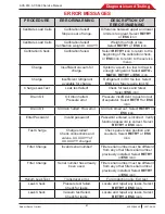


ACS 653, ACS 663 Service Manual
SP00D00624
2021-04-08
Robert Bosch GmbH
51
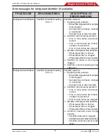
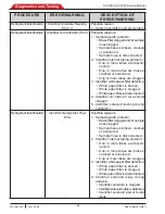
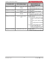
Diagnostics and Testing
10. Verify the oil drain solenoid isn’t leaking
the vacuum. Place a finger over the end of
the oil drain tube and check for suction. If
a suction is detected, replace the oil drain
solenoid. Retest.
11. Disconnect the manifold end of the
compressor oil return line and check
for pressure coming from the manifold
(with compressor running). If pressure is
detected at the compressor oil return line
connection on the manifold, replace the
compressor oil return solenoid. Retest.
12.
Verify the accumulator/oil separator bowl is
tight. Tighten and retest if loose.
•
If not loose, remove the accumulator/oil
separator bowl and check the condenser
coil connections to ensure they are tight.
• If loose, tighten, reassemble, and retest.
13. Verify the compressor oil separator bowl is
tight and the O-ring is installed.
• If the compressor oil separator bowl is
loose, retighten and retest.
• If the O-ring is missing, install a new
O-ring, reassemble, and retest.
14. Reinstall the condenser coil and compressor
oil separator bowl; do not reinstall the
system oil separator bowl.
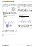
15. Access the service menu and select the
Output Test option.
16. Scroll to the
Compressor
and turn it on.
Once the compressor is running check the
condenser coil connections, condenser coil
tubing, and compressor oil separator threads
for leakage with a soapy water solution or
other leak detection fluid. Remove the
leaking component and verify the O-rings
are in place and not cut or damaged.
The O-rings and mating parts should be
lubricated prior to assembly. Repair any
leaks found and retest.
NOTE:
Limit the amount of time the compressor
is running, as it will be pulling in air and adding
it to the ISV. Be sure to purge the air from the
ISV once the machine is repaired.
17. If the unit doesn’t complete clearing, test the
compressor as reccomended procedure.
Refer to
Compressor Troubleshooting
in the
Compressor section of this manual.
Will Not Recover
NOTE:
The compressor should be running
during this test. If it does not run, refer to
Compressor troubleshooting
in the Compressor
section of this manual.
1. Verify there is pressure reading on the
gauges.
• If pressure is present, the service hoses
are connected correctly.
• If pressure is absent, the service hoses
are connected improperly or there is a
restriction. Clear and reconnect service
hoses.
2. Display the accumulator pressure (enable
“display title info” in maintenance menu).
• If there is no pressure, inspect inlet
valves, recover solenoid, and check
valves.
• If pressure seems normal at the
accumulator, inspect oil return solenoid
(S13), and compressor.
NOTE:
The recover solenoid (S11) is controlled
to maintain a maximum of 2.5 bar (35 psi) in
the accumulator.
3. Verify operation of the recover check valve.
Replace as needed.
4. Check the compressor for suction and
discharge performance.
5. Remove the filter and inspect all fittings
and gaskets to verify that no obstructions
exist. Replace/repair gaskets as needed
and reinstall filter.
6. Verify the accumulator transducer is
functioning properly by attaching a calibrated
gauge to the service port and compare
readings to those on the manual gauge.
The readings should be within the
specifications on the transducer ID plate.
7. Check the oil return (S13) solenoid for
bleed-through and proper operation. Repair
as needed.
8.
Check Tank Liquid solenoid, evacuating the
tank with a recovery service unit in advance.
9.
If problem still exists, check the vacuum (S9)
solenoid, as applicable.
NOTE:
If the compressor fails to operate, refer
to
Compressor Troubleshooting
.


