


ACS 653, ACS 663 Service Manual
SP00D00624
2021-04-08
Robert Bosch GmbH
27
Introduction
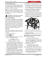
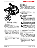
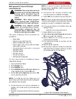
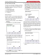
34. Remove the cap (13) and the visible screw
from the hole (see Figure 1-23).
35. R e m o v e t h e c o n t r o l p a n e l ( 1 4 )
(see Figure 1-23).
14
13
Figure 1-23 Control panel removal
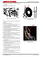
36. Connect the air flow harness to the
P1
connector of the control board.
37.
Re-fix the control panel (14).
38.
Screw back the screw and place the cap (13).
39. Insert the rear cover so that the 4 holes on
the sides the cover fit into the 4 clips on the
machine. Push down to hook the rear cover.
40. Close the service rear door.
41. Reinstall the plastic frontal cover and
fix it by 6 screws (1) and the 2 ones (2)
(see Figure 1-20).
42. Attach new high- (red) and low-side (blue)
service hoses with quick couplers. Tighten
at 7.9 Nm torque.
43. Connect the unit to a power source and
place the power switch on.
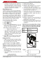
44. Follow the instructions on display to replace
filter (refer to “Filter Maintenance” in the
Maintenance section) and vacuum pump oil
(refer to the “Vacuum Pump Maintenance”
in the Maintenance section).
NOTE:
If the A/C unit never recovered refrigerant
then it won‘t be asked to replace the filter nor
replenish the pump oil.
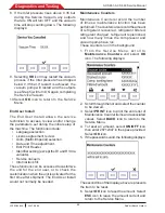
45.
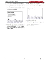
The conversion procedure is finished when
the display shows:
THIS AC UNIT IS NOW CONVERTED
TO R-1234YF
46. Select
OK
icon to complete the process.
47.
Remove the refrigerant identification decal
from the right side of the enclosure replacing
it with the new one.
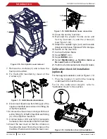
48.
Perform air flow calibration. Refer to
“
Air Flow Calibration
” in the Diagnostics and
Testing section.
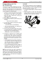
49. Perform 3 kg tank refill and then a
“Periodic Leak Test” to verify system
tightness (refer to the “Pressure Decay Leak
Test” in the Maintenance section)


