ACS 653, ACS 663 Service Manual
SP00D00624
2021-04-08
Robert Bosch GmbH
104
Plumbing and Mechanical
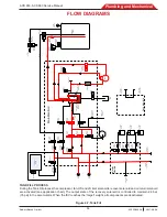
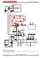
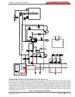
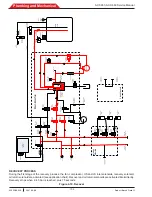
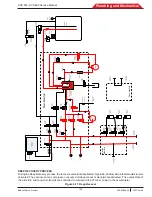
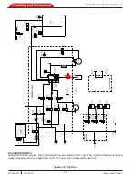
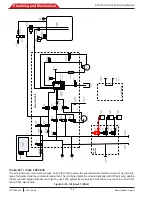
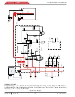
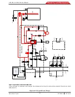
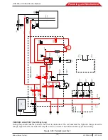
Figure 4-12. Oil Drain
OIL DRAIN PROCESS
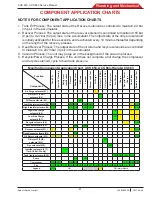
During the Oil Drain process, the unit pressurize the accumulator until 1.1 bar. Then oil drain solenoid opens and
release pressure and oil (see application chart). The oil amount is measured by load cell.
Lo
w
S
id
e
S
erv
ic
e
H
ose
V
ac
uu
m
P
ump
C
om
pr
es
so
r
O
il
1
In
je
ct
B
ott
le
O
il
D
ra
in
B
ott
le
H
igh
S
id
e
S
er
vi
ce
H
ose
Inj
ec
tio
n
M
an
ifo
ld
Acc
um
ul
at
or
Tr
an
sd
uc
er
D
eep
R
ec
ov
er
S
ol
en
oi
d
H
S
G
au
ge
V
ac
uu
m
P
um
p
Ex
ha
ust
Fil
te
r/D
rie
r
H
igh
Pr
ess
ure
C
ut
ou
t S
w
tich
M
ai
n
M
an
ifo
ld
P
um
p
Ex
hau
st
C
he
ck
V
al
ve
O
il
R
et
urn
S
ol
en
oi
d
LS
C
ha
rge
So
leno
id
LS
C
ha
rge
C
he
ck
V
al
ve
H
S
Cha
rge
So
leno
id
H
S
Cha
rge
C
he
ck
V
al
ve
R
ecy
cl
e
So
leno
id
R
ec
ov
er
C
he
ck
Va
lv
e
R
ec
ov
er
So
leno
id
H
ea
t Exc
han
ge
r /
Sys
te
m
O
il
S
ep
ar
at
or
C
om
pr
ess
or
O
il
S
ep
ar
at
or
LS
In
le
t
So
leno
id
H
S I
nl
et
So
leno
id
Va
cuu
m
So
leno
id
O
il I
nj
ec
t 1
So
leno
id
O
il I
nj
ec
t 1
C
he
ck
V
al
ve
O
il
D
ra
in
So
leno
id
S
erv
ic
e
P
ort
ID
O
rif
ic
e
R
ef
rig
er
an
t
Iden
tif
ie
r
R
I F
ilt
er
O
il I
nj
ec
t 2
So
leno
id
O
il I
nj
ec
t 2
C
he
ck
V
al
ve
D
ye
In
je
ct
So
leno
id
D
ye
In
je
ct
C
he
ck
V
al
ve
O
il 2
In
je
ct
B
ott
le
D
ye
In
je
ct
B
ott
le
LS
G
au
ge
ID
S
ol
eno
id
Lo
w
S
id
e
Tr
an
sd
uc
er
A
ir
P
ur
ge
S
ol
en
oi
d
Te
m
p.
S
en
so
r
A
ir
D
iff
us
er
C
on
ta
m
in
at
io
n
P
ort
V
ap
or
Li
qu
id
In
te
rna
l
Tan
k
Tan
k
Li
qu
id
S
ol
en
oi
d
P
re
ss
ur
e
R
eli
ef
IS
V
P
re
ss
ur
e
Tr
an
sd
uc
er
V
ap
or
C
he
ck
V
al
ve
Lo
w
S
id
e
S
to
ra
ge
P
ort
H
igh
S
id
e
S
to
ra
ge
P
ort
F
lu
sh
M
an
ifol
d
RI variants only


