User’s Manual
63
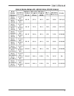
Table 6-5: Module Ratings: 690 VAC Drives (1090 VDC Setpoint)
B
ASE
M
ODEL
N
UMBER
C
ONTROL
V
OLTAGE
B
RAKING
P
OWER
(P
EAK
)
B
RAKING
C
URRENT
(P
EAK
)
B
RAKING
C
URRENT
(RMS)
D
UTY
C
YCLE
M
INIMUM
R
ESISTANCE
F
USING
M3452-
U200YK6
115-120
VAC
300 HP
200 A
200 A
100%
5.50 Ω
A100P200
M3452-
U300YK6
115-120
VAC
440 HP
300 A
300 A
100%
3.60 Ω
A100P300
M3452-
U600YK6
115-120
VAC
875 HP
600 A
300 A
50%
1.95 Ω
A70QS600
M3452-
U800YK9
115-120
VAC
1170 HP
800 A
400 A
50%
1.40 Ω
A70QS800
M3452-
U1200YK10
115-120
VAC
1750 HP
1200 A
600 A
50%
0.91 Ω
A70QS800
M3452-
U1600YM14
115-120
VAC
2300 HP
1600 A
1200 A
75%
0.68 Ω
N/A
6.2.
W
ATT LOSS
Table 6-6: Watt Loss
U
NIT
P
EAK
C
URRENT
C
ONTROL
P
OWER
W
ATT
L
OSS
H
EATSINK
W
ATT
L
OSS
200 A
55 W
500 W
300 A
55 W
750 W
600 A
55 W
750 W
800 A
55 W
1000 W
1200 A
55 W
1440 W
1600 A
55 W
2500 W
6.3.
C
ERTIFICATIONS
The following modules with the R7EIP or R7PDP option are UL and cUL listed by
Underwriter's Laboratories under file number E204386 for UL508C Power Conversion
Equipment:
•
M3452 200A, 300A, and 600A models
▪
L, H, C System Voltage Rating codes.
•
All M3452 M14 1600A models.
▪
L, H, C, Y System Voltage Rating codes.
6.4.
UL
508A
S
HORT
C
IRCUIT
C
URRENT
R
ATING
When braking transistors are used with Underwriters Laboratories listed or recognized
drives, the short circuit current rating (SCCR) is determined by the SCCR rating of the
attached drive.
6.5.
F
USE
/C
IRCUIT
B
REAKER
S
IZING AND
R
ATING
Each module (except the 1600 amp M14 chassis) comes equipped with its own
internal DC bus fuse.
If the fuse happens to fail, it is not recommended to replace
Summary of Contents for M3452
Page 14: ...M3452 vR7 EIP PDP 14 This page intentionally left blank ...
Page 19: ...User s Manual 19 Figure 3 2 Customer Connections in K9 Chassis CUSTOMER I 0 CONNECTION ...
Page 21: ...User s Manual 21 Figure 3 2 Customer Connections in M14 Chassis CUSTOMER I O CONNECTION ...
Page 24: ...M3452 vR7 EIP PDP 24 Figure 3 6 I O Hookup with R7 EIP PDP Communication ...
Page 26: ...M3452 vR7 EIP PDP 26 Figure 3 8 24VDC Power Connection ...
Page 58: ...M3452 vR7 EIP PDP 58 This page intentionally left blank ...
Page 66: ...M3452 vR7 EIP PDP 66 Figure 6 3 M3452 K9 Chassis Dimensional Outline Drawing ...
Page 68: ...M3452 vR7 EIP PDP 68 Figure 6 5 M3452 M14 Chassis Dimensional Outline Drawing ...
Page 75: ...User s Manual 75 NOTES ...
Page 76: ...M3452 vR7 EIP PDP 76 This page intentionally left blank ...
Page 77: ......
Page 78: ......
Page 79: ......

