User’s Manual
49
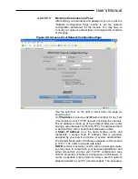
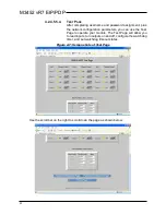
Note that the 12 channels of this module are divided into 3
groups (ports) of 4 channels each. Each port represents one
pluggable I/O terminal block (6 screws). Port Number 0 refers
to I/O channels 0-3, port number 1 refers to channels 4-7, and
port number 3 to channels 8-11. The state of a channel is
indicated by the color of the simulated LED’s and the text
“ON” or “OFF”.
These states also reflect the actual yellow I/O status LED’s of
the module.
IMPORTANT:
The input state indication only reflects the
state of the inputs at the moment this screen is invoked and
this does not continuously update.
You can click your browser’s refresh button to get a new input
update. The output states are updated each time you click the
channel’s On/Off button. You can use the On/Off buttons
adjacent to the channel number to turn the outputs of 982EN
and 983EN modules ON or OFF.
The output state indication is updated each time you click
On/Off.
IMPORTANT: Use caution with the output function, and
only toggle the state of outputs on channels 8-11.
Writing 1’s to channels 0-7 will override the actual output
values from the M3452 monitoring bits.
A watchdog timeout is triggered at the port if no channel read
or write occurs for one or more channels of a port within the
time period specified. You can use the Port watchdog Timer
Control to specify Time from 0001h to FFFEh seconds (1 to
65534s). A Time value of 0000h or FFFFh (0 or 65535) will
disable the timer for the port I/O. You can also define the state
the outputs are to assume following a timeout via the lower 4
bits of the 16-bit value entered into the State field for the port.
Enter FFFFh into the State field to leave the port outputs
unchanged following a timeout. Note that the lower order bit
(bit 0) corresponds to the lowest channel number for the port,
bit 1 to the next channel number, and so on. Except for
FFFFh, the first three hexadecimal digits of State are ignored
(each port has only 4 channels and the least significant nibble
(4-
bits) of the State value are all that’s required for control.
For example, e
nter a state value of “0000” to turn OFF (open)
all port outputs (failsafe state) upon watchdog timeout. You
would enter “000F” to turn all port outputs ON upon watchdog
timeout. Upon power-
up, the green “Run” LED should light.
This indicates the unit is operating normally. A continuous
blinking Ru
n LED indicates “wink” ID mode. If the Run LED
remains OFF and correct power has been applied, then either
the internal power supply has failed or a fatal processor error
(firmware) has occurred
Summary of Contents for M3452
Page 14: ...M3452 vR7 EIP PDP 14 This page intentionally left blank ...
Page 19: ...User s Manual 19 Figure 3 2 Customer Connections in K9 Chassis CUSTOMER I 0 CONNECTION ...
Page 21: ...User s Manual 21 Figure 3 2 Customer Connections in M14 Chassis CUSTOMER I O CONNECTION ...
Page 24: ...M3452 vR7 EIP PDP 24 Figure 3 6 I O Hookup with R7 EIP PDP Communication ...
Page 26: ...M3452 vR7 EIP PDP 26 Figure 3 8 24VDC Power Connection ...
Page 58: ...M3452 vR7 EIP PDP 58 This page intentionally left blank ...
Page 66: ...M3452 vR7 EIP PDP 66 Figure 6 3 M3452 K9 Chassis Dimensional Outline Drawing ...
Page 68: ...M3452 vR7 EIP PDP 68 Figure 6 5 M3452 M14 Chassis Dimensional Outline Drawing ...
Page 75: ...User s Manual 75 NOTES ...
Page 76: ...M3452 vR7 EIP PDP 76 This page intentionally left blank ...
Page 77: ......
Page 78: ......
Page 79: ......


