M3452 vR7 EIP/PDP
40
cables, these are generally reserved for short runs and patch
applications less than 6 meters.
Currently there are two types of shielding employed in Category 5
STP cable: single-shielded cable and double-shielded cable. Both
of these cables have the same core and jacket as UTP cables, but
also include a thin foil outer shield that covers all four twisted-wire
pairs. Some variations will also include a drain wire that encircles
the outer foil. The double-shielded version adds an outer wire
screen that wraps around the foil shield and also functions as a drain
wire. The drain wire or wire screen typically makes contact at each
end of the cable with the metal shield around special RJ45 plug
connectors. The metal shield of these connectors then makes
contact with the metal shield of shielded RJ45 sockets. The socket
shield may make direct contact with earth ground, or it may be
capacitively coupled to earth ground. In the Acromag 9xxEN
modules, this shield contacts earth ground via a high voltage
capacitor and transient voltage suppressor. In addition to minimizing
radio frequency and electromagnetic interference, this arrangement
also has the added benefit of enhanced protection from ESD
(Electro-Static Discharge).
4.2.4.5.5.
W
EB
B
ROWSER
C
ONFIGURATION
P
AGES
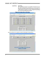
This module supports EtherNet/IP and Modbus TCP/IP. You may
use your own method to issue EtherNet/IP or Modbus commands to
this module as required, or you may use a standard web browser,
as these modules have built-in web pages that allow you to setup
and control the module. Simply execute your web browser, type the
IP address assigned to your module in the “Address” window
(http://128.1.1.100/ for our example), click [Go], and you will be
presented with a Home Page window similar to that shown below.
Summary of Contents for M3452
Page 14: ...M3452 vR7 EIP PDP 14 This page intentionally left blank ...
Page 19: ...User s Manual 19 Figure 3 2 Customer Connections in K9 Chassis CUSTOMER I 0 CONNECTION ...
Page 21: ...User s Manual 21 Figure 3 2 Customer Connections in M14 Chassis CUSTOMER I O CONNECTION ...
Page 24: ...M3452 vR7 EIP PDP 24 Figure 3 6 I O Hookup with R7 EIP PDP Communication ...
Page 26: ...M3452 vR7 EIP PDP 26 Figure 3 8 24VDC Power Connection ...
Page 58: ...M3452 vR7 EIP PDP 58 This page intentionally left blank ...
Page 66: ...M3452 vR7 EIP PDP 66 Figure 6 3 M3452 K9 Chassis Dimensional Outline Drawing ...
Page 68: ...M3452 vR7 EIP PDP 68 Figure 6 5 M3452 M14 Chassis Dimensional Outline Drawing ...
Page 75: ...User s Manual 75 NOTES ...
Page 76: ...M3452 vR7 EIP PDP 76 This page intentionally left blank ...
Page 77: ......
Page 78: ......
Page 79: ......


