M3452 vR7 EIP/PDP
30
The dynamic master switching sequence should follow these steps:
•
Disable all modules by opening the “Enable” input. Bus
regulation stops.
•
Close “Master Select” contact on a single module.
•
Ensure that only one Master/Slave Status contact is closed in
the system, indicating that only one module is master.
•
Enable all modules. Bus regulation resumes.
4.2.4.
F
IELDBUS
I/O
4.2.4.1.
M
EMORY
M
AP
The R7EIP and R7PDP modules have an embedded digital network
module. This module is an Acromag 983EN-2012 or 983DP-2012. The
configuration files and manuals for these modules are available on either
the Bonitron website or the Acromag website.
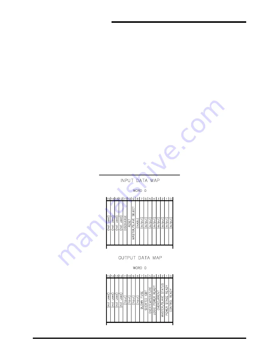
The memory map shows the position of the control and status bits in
relation to the base address on the network. Detailed descriptions of each
bit and register are in the previous sections.
The memory map is word based, each word using 16 bits.
This module has bidirectional connections for inputs and outputs. Care
must be taken when programming, as input bits will override the output
bits if set in the wrong addresses.
Figure 4-1: M3452R7 Memory Map
Summary of Contents for M3452
Page 14: ...M3452 vR7 EIP PDP 14 This page intentionally left blank ...
Page 19: ...User s Manual 19 Figure 3 2 Customer Connections in K9 Chassis CUSTOMER I 0 CONNECTION ...
Page 21: ...User s Manual 21 Figure 3 2 Customer Connections in M14 Chassis CUSTOMER I O CONNECTION ...
Page 24: ...M3452 vR7 EIP PDP 24 Figure 3 6 I O Hookup with R7 EIP PDP Communication ...
Page 26: ...M3452 vR7 EIP PDP 26 Figure 3 8 24VDC Power Connection ...
Page 58: ...M3452 vR7 EIP PDP 58 This page intentionally left blank ...
Page 66: ...M3452 vR7 EIP PDP 66 Figure 6 3 M3452 K9 Chassis Dimensional Outline Drawing ...
Page 68: ...M3452 vR7 EIP PDP 68 Figure 6 5 M3452 M14 Chassis Dimensional Outline Drawing ...
Page 75: ...User s Manual 75 NOTES ...
Page 76: ...M3452 vR7 EIP PDP 76 This page intentionally left blank ...
Page 77: ......
Page 78: ......
Page 79: ......


