


M3452 vR7 EIP/PDP
34
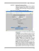
than the switches. The internal EEPROM setting is modified via the
Set Slave Address command. Powering up with switches set to 255
(FFh) will cause the internal EEPROM setting to revert back to 126
(7Eh), which may be used to re-commission the module. If both the
internal EEPROM address and the switches are set to 126 upon
power-up (this is the initial state from the factory), the module will
await the Set Slave Address command before completing
initialization and assuming the data exchange mode.
IMPORTANT!
(Address Setting)
:
The internal EEPROM address setting and
external switch setting is 126 from the factory. As such, the
module will await the Set Slave Address command following
power-up and will not proceed to exchange data, unless the
external switches are instead set to an address from 0-125, or the
internal setting is changed to an address from 0-125 via the Set
Slave Address command.
PROFIBUS Character:
11 bits (1 start bit + 8 data bits + 1 even
parity bit + 1 stop bit). Applies to all bytes, including frame bytes.
Bus Idle State:
“1” (a start bit causes line to go to “0”). An idle state
of at least 33 Tbits (sync-time) must be provided between
messages.
•
Note: 1Tbit at 12Mbaud = 1/12000000bit/sec = 83nsec.
Ident_Number:
06F3 Hex (981PB-2012), 06F2 Hex (982PB-2012),
06F1 Hex (983PB-2012).
GSD File:
ACRO06F1.GSD (983PB-2012).
Network Capacity:
Multi-drop up to 31 modules, plus a host,
without a repeater. Up to 125 modules plus a host if four repeaters
are used (one for every 31 nodes).
4.2.4.4.2.
LED
I
NDICATORS
Run (Green) -
Constant ON if power is on and unit is OK. Flashing
ON/OFF indicates unit is performing diagnostics (first few seconds
after power-up), or has failed diagnostics (after a few seconds).
Bus (Yellow)
–
ON indicates unit has completed its initialization
sequence and is in the data exchange mode on the network.
Output (Yellow, One Per Output)
–
ON if output relay is ON
(closed).
4.2.4.4.3.
N
ETWORK
C
ABLING
The network connection is a
9-pin D-Sub connector (female) with
metal housing and 4-40 jack screw support. Pin out is detailed
below.
Summary of Contents for M3452
Page 14: ...M3452 vR7 EIP PDP 14 This page intentionally left blank ...
Page 19: ...User s Manual 19 Figure 3 2 Customer Connections in K9 Chassis CUSTOMER I 0 CONNECTION ...
Page 21: ...User s Manual 21 Figure 3 2 Customer Connections in M14 Chassis CUSTOMER I O CONNECTION ...
Page 24: ...M3452 vR7 EIP PDP 24 Figure 3 6 I O Hookup with R7 EIP PDP Communication ...
Page 26: ...M3452 vR7 EIP PDP 26 Figure 3 8 24VDC Power Connection ...
Page 58: ...M3452 vR7 EIP PDP 58 This page intentionally left blank ...
Page 66: ...M3452 vR7 EIP PDP 66 Figure 6 3 M3452 K9 Chassis Dimensional Outline Drawing ...
Page 68: ...M3452 vR7 EIP PDP 68 Figure 6 5 M3452 M14 Chassis Dimensional Outline Drawing ...
Page 75: ...User s Manual 75 NOTES ...
Page 76: ...M3452 vR7 EIP PDP 76 This page intentionally left blank ...
Page 77: ......
Page 78: ......
Page 79: ......


